Winter project: upgrading time! (R6 forks and more...)

Interesting setup Bosco, if I had a bigger place I would go this route. But since my space is limited I want to go for a bench mounted solution.

Btw, that anti rotation bolt, is that friction only or is there a indent?
 
Interesting setup Bosco, if I had a bigger place I would go this route. But since my space is limited I want to go for a bench mounted solution.

Btw, that anti rotation bolt, is that friction only or is there a indent?
Just friction. It doesn’t hold that well, but for the VW engine it’s ok. For an XS motor it may not hold if the motor were rotated 90 degrees. The engine stand has holes at 45 degree intervals and a pin locks it in place.
 
Outstanding work you might be the best fabricator around here


made a new sidestand of chromoly tubeView attachment 207033....its lighter


View attachment 207032

no major modifications to the bike this winter. Planning to build a new shed, that takes all the energy. One thing im working on to get the bike ready for the next season is to de-carbon the engine. I saw lots of build up through the sparkplug holes. Might explain the 'pinging' i believed i heard last fall. In order to work on the engine im making this:
View attachment 207034

should be able to bolt it to the bench and rotate it.


Thinking out loud
If I get this right you have one mount point on upper engine casing half
and one on lower engine casing half ...After the cylinder and head is off is it not impossible to split the bottom end
Separating cases
 
Yeah the new shed is a big project for me. Lots to learn on working with wood and concrete instead of steel haha.

Yeah I might not split the cases this time due to time constraints. I would like to take a peek since I've never had it open since I own the bike (12+years). Don't want to spend to much time on the bike with the shed waiting.

Anyway I designed the lower arms of the engine stand to be removable. Should allow the bottom end to be pulled.
engine stand v1-2.JPG
 
I perhaps have been to close to excavators to long ... so I would beef up the thickness of the design
Especially if the engine is turned 90 degrees there can be a need for more stiffness

Secondly more important perhaps
At the second picture if i get this right the engine is clamped in a point far back at bit off the center of gravity that means that the motor has a tendency to rotate around that pivot point. It is doable if one clamps hard enough at that point. But hard clamping means more load.

I comes down to how much rough stuff that will be done in that engine stand ( again excavators )
But the clamping -- the torque arm -- and Muscles can insert loads at the pivot point

Perhaps the option of an extra support in some Positions like a Jack
 
Don't really follow you Jan..

About the thickness, can't go thicker because than it would block some of the bolt/nuts required to disassemble the lower half.

Regarding the model. Yeah super lucky with this. Some french guy drew his entire XS tracker. The amount of details are crazy. It's open source and you can find it on grabCad. I just used his model

Dont have CAD here that quickly ..Trying to put it in words in Bad English
Mechanics statics --- has 2 aspects Force equilibrium and Moment. equilibrium

Illustrating with a game the big boys in the excavator shop had selecting the men from the boys .
Not many could do it. Few tried
A sledge hammer is standing on the shop floor with the handle vertical hammer head at the floor
Kissing the sledge the game was called .One grabs the handle at the top and with your wrist turns it backwards .In a circle
The hammer has the same weight all the time but at the point 90 degrees out back one has to have very strong hands and wrists
It is because the hammer head is extended backwards about one meter
I dont remember what sledge it was 8 - 10 Kg

Lets say for the reasoning 8 kg For equilibrium the force to keep the sledge up is the same 8 kg + the handle but the Torque the wrist must handle is
1m x 8 kg. The torque is less in every other angle because the torque arm length is smaller
At the starting point not much wrist strength is needed . Nor at the end when the kissing of the sledge is done

If one did not have strong enough hands one could not control the motion and the hammer head can hit your face and teeth ( over the shoulder )
and one has to abort get the face out of the way to the accompanying laughter of the collegaues with words. Shouted.
Some of the big boys can do it but not many.
I am not even close myself.

So the point
The motor for equilibrium wants to rotate around the pivot point the hand in the sledge hammer game .. and the force needed upwards is the weight of the motor ..
But the torque arm is between the center of gravity to the rotation point .. If that is larger a large Torque is needed,
If i get this right here it will be about 300 mm between the center of gravity and pivot point

I cannot do it with the Kissing the sledge hammer but I do it with smaller hand sledges as a workout For strengthening the wrists. At times
If you grab a hammer say 1. 5 kg hold it verticallly with the hammer head up 12 o clock and then slowly rotate it clockwise.
You'll notice at 3 o clock it takes more strength to hold it there .

If i get this rigt the same Phenomena with the engine stand the longer the distance between the Pivot point and center of gravity the larger the moment at the pivot point..( Strong hands ) Inserting more load.
 
With corona in my system I had to read it a couple of times but I think I get it haha.

Well the cad model wasn't usable for determining the centre of gravity of the engine. I just eyeballed it. And rotating it should be done with most parts removed from the engine, that's what my gut feeling tells me. And I should get a feel for the sturdiness of the engine stand before ripping hard on some engine parts for sure!

But this design isnt completely out of nothing. I saw pictures where Jerry VD heiden (heiden tuning) uses a similar jig. Also at the XS club here in the Netherlands where I took a engine coarse recently they had engine stands with sort of this mechanism.

We'll have to find out haha. Can always use a grinder and welder to make it work ;)
 
Did some small things on the XS the last few weeks. Still trying to get everything done and ready for the road.

Made a bit nicer enricher (choke) set- for the Keihin CKV 34 carbs. Haven't tested it on the bike yet but im hoping the steps will improve the function.
IMG_20220219_212034311.jpg


IMG_20220225_174628350.jpg


The popo convinced me very ''kindly'' to make a new licence plate holder. I told them I already had plenty of projects.... but they really insisted haha. Made the alu plates and had them welded at a local shop. Would be nice to have a AC tig myself.

IMG_20220211_143243728.jpg


IMG_20220212_171531735.jpg


Also did some searching for a remote idle control screw for the carbs. The original one is at the bottom and impossible to reach when riding. Last year i found that making very minor adjustment would be nice. This model is almost a plug and play sollution. Only need to make a simple bracket.

The part number: 160210005 from kawasaki.

IMG_20220213_140950250.jpg

IMG_20220213_141006375.jpg


And a video showing the workings of the choke:


more to come on the engine stand and top end rebuild...
 
More posts later, but for now I got a question. I'm trying to finish up the engine rebuild. And am struggling with the alignment of the camshaft.

I have followed the great tread by Gary

https://www.xs650.com/threads/xs650-top-end-buildup.52041/

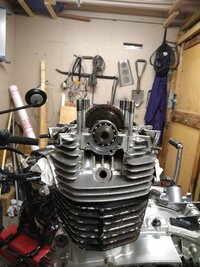
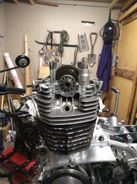
But I cannot seem to get the "perfect" alignment of the cam. Below pictures of two situations. One seems left of 12 o'clock, the other to the right . Accordingly, the punch mark is below of above the face of the head. Which tooth should I get??
IMG_20220316_221134653.jpg


IMG_20220316_224517053.jpg


Background info, new base and head gasket. Not a new cam chain. Just slid this on off/on the camshaft. Camchain tensioner not installed yet. Crank put in TDC
 

Attachments

  • IMG_20220316_221129489.jpg
    IMG_20220316_221129489.jpg
    307.4 KB · Views: 82
  • IMG_20220316_224509982.jpg
    IMG_20220316_224509982.jpg
    314.3 KB · Views: 83
O and yes, I take the slack out of the chain on the front side. However I was expecting more slack in the whole chain. When I put the bearings on the cam it already seems pretty tight. It does seem to be running straight in the guides though. Haven't done this work in a few years so kinda lost my reference..
 
Back
Top