Wiring again

nb1914

XS650 Addict
Messages
167
Reaction score
0
Points
16
Location
UK gloucester
Deep breath……..ok what do i have, from the stator i have a loom with 4 wires

3x brown ( PO has jointed so assume these are white at the stator )
1x back ( assume earth )

I also have 2 shorter wires both White

I have a REG/REC with
3x white
1x red
1x black
1x green
1x brown

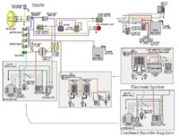
From the tech section wiring diagrams i can deduce that from bike wiring that, i would do as follows

connect the 3x brown from the stator to the 3x white on the REG/REC, connect the black from the stator to earth somewhere.

I would connect the Red from the REG/REC to the battery positive maybe after an inline fuse. I would connect the black from the REG/REC to earth somewhere. I would connect the brown from the REG/REC to the positive rail after ignition switch.

That leaves the green wire from the REG/REC and the 2 shorter white leads from the stator. from the tech section one simplified diagram shows the green and another brown connection from the REG/REC connecting to something which isn't labelled.

previous to this the bike had separate Regulator and Rectifier modules. At present I'm assuming that the green and another brown connection go to the 2 shorter white cables from the stator, would that make sense and what are they for, does it matter which one green goes to or brown goes to.
 
The green wire from Rec/Reg goes to one side of your brushes on the Alternator. The brown wire you mentioned going from the Rec/Reg to the positive rail should also splice off and supply the other side of the brushes on the Alternator. See the attached diagram.
 

Attachments

  • wiring2.jpg
    wiring2.jpg
    94.1 KB · Views: 625
Well maybe not so much. What Willis described is how you wire the brushes on an '80 and later stator. The '79 and earlier ones are wired differently. What you need to determine is which stator you have and also what type of reg/rec you have. The two systems use different types of regulators as well.
 
ah , I'm sure its an 1980 stator well thats the bike first registration. I'm edging my bets that the
PO used 3 brown to keep some continuity i.e. the stator AC power output, well i hope so i guess ill wire it and see if anything smokes but i guess if the rectifier output is correct with some throttle i should see something like 14v at the battery ?
 
As 5twins said , do a little bit more investigation. The '80 UK model may have a different stator than the US '80 model. You mentioned separate reg and rec, also does your bike have points or TCI? That would be another indication for using '79 and earlier wiring diagram.
 
A local kid had me look over his 650 when he first got it. It is a '78 with the early type charging system but the P.O. had installed a later model's combined reg/rec unit. It charged alright but way high, like 15+ volts. I told him that wasn't right and we needed to address the situation. He had some guy at work look at it and he told him it was fine. The kid got a little over 600 miles on the bike before the charging system fried.

So, go ahead and wire yours up. It probably won't make smoke immediately, lol. I'll just advise you to start setting money aside now for the expensive charging system components (rotor, maybe stator too) you may need to buy in the near future.
 
ok i looked at the posting musket sent and the 4 posting photo 3 is what i have, this suggests that the brushes have a notation i,e, in that photo it states the bottom wire is +12v, i guess that would be the regulator brown wire and then the other brush goes to green. i can buzz these wires out to make sure they equate to the 2 shorter wires in the stator loom. I will also check for approx 5 ohm resistance between all the brown wires coming from the stator. When i get it together and running i will check that I'm not over charging, what should the voltage be with a good stator spinning ?
 
The bottom power wire should be green, the top wire black, ground. There should be no continuity between the white stator wires. The 5 ohms test is for the sliprings on the rotor.
 
you might find some useful info in this vid
12v+ feeds the outer ring of the rotor (green wire ) and the inner ring (black wire ) goes to ground to complete the circuit.

 
thanks, confused now , the wiring diags in the tech section show the 2 wires from a combined reg/rec going to the brushes as being green and brown. The brown also goes to the positive rail after the ignition switch. Is the green then the earth via the reg/rec ?
 
i guess i could apply a voltage across those 2 shorter wires that i suspect are the brush connections and see if i get a magnetic pull on a feeler gauge near the case
 
First you got to figure out what you are working with. There are a lot of mismatched parts on these bike. Here are a couple diagrams to look out and 1980 to 1983 had a oval black pickup on alternator others don't. The first one gives you all the years broke down
 

Attachments

  • wire650.jpg
    wire650.jpg
    135.4 KB · Views: 423
  • wiringXS01_zpsedd450f2.jpg
    wiringXS01_zpsedd450f2.jpg
    310.6 KB · Views: 619
  • 777.jpg
    777.jpg
    83.1 KB · Views: 1,132
  • 1981simplifiedwiringpart3.jpg
    1981simplifiedwiringpart3.jpg
    48.8 KB · Views: 4,361
thanks, confused now , the wiring diags in the tech section show the 2 wires from a combined reg/rec going to the brushes as being green and brown. The brown also goes to the positive rail after the ignition switch. Is the green then the earth via the reg/rec ?

Your model isn't a 79 so the colour or the 2 wires feeding the rotor may be different but the principle is exactly the same. The rotor needs one 12v+ feed and the other wire will go to ground to create the magnetic energy field . Depending on the model year the ground wire will either go straight to the chassis or it will be regulated by the regulator on later models with the combined rectifier and regulator.

Rather than going by the colour of the wires you should always check which componants you are connecting together ,using a multimeter. One should never ,ever trust the colour of the wiring, especially when the wiring has been modified by a previous owner. If you get it wrong you could end up with your bike in flames
 
..
ok i have, from the stator

3x brown ( PO has jointed so assume these are white at the stator )
1x back ( assume earth )
2 shorter wires both White

I have a REG/REC with
3x white
1x red
1x black
1x green
1x brown
.

If you have a 1980 bike with a combined reg/rectifier
You should have 6x wires going into , (and coming out of ), the stator connector block
3x white
1x green
1x brown

There should also be a seperate blue wire which comes directly from your neutral switch on the top of the crankcase to the neutral warning light and a seperate yellow wire which controls the starter motor relay which is often capped off

The brown wire is a 12v+ (switched) live feed directly from your ignition switch to the outer brush on your stator. ( It is live when you switch your ignition on.)
The 12v+ goes through the brush to the outer Rotor ring , through the Rotor winding (which is basically one big coil ), then comes out at the inner Rotor ring and back out the other brush to the green wire.
The green wire goes from the inner Rotor ring,.. via the stator brush to your regulator/rectifier via the stator block .This is the wire that the regulator grounds when your battery needs charging . This is how your charging system is controlled .

The 3x white wires come directly from the Stator windings and should all go directly to the rectifier /regulator. (These are the wires that carry your AC voltage to the rectifier which converts it to DC volts)

Because someone has mucked about with the stator wiring you cannot trust that any of the wires go where they should do no matter what colour they are because they are clearly not standard.
If you cannot use a multimeter to do some simple continuity checks to establish beyond doubt which wire attaches where on your stator , you will need to remove the side cover and see exactly what is going on in there.
My advice would be do not just join random wires to a 12v battery to see what will happen .
 
Last edited:
don't forget that the 7th wire doesn't come out of the stator but from the neutral switch on the crankcase. It does end up in the stator terminal block though which makes the 7th wire.
 
Six wires from the stator is standard. The 7th wire in the harness (if there is one) doesn't run to the stator, it goes to the neutral switch on top of the motor. Stock early stator wires would be 3 whites, a yellow, a green, and a black. The yellow wire is a sensor wire that runs to the safety relays for the headlight and starter. Once the alternator starts putting out a charge, that output is read on the yellow wire by the relays and they trip. I think it takes 4 or 5 volts to trigger them. The green is regulated power from the regulator to the outer brush. Black is a ground wire to the inner brush, but probably not a ground wire in the way you're thinking.

The inner brush on the older stator is grounded on it's own, through it's 3 mounting screws. They ground it to the stator housing, which grounds to the motor block, which grounds to the frame. The black wire connected to that brush isn't delivering a ground to it, it's actually picking one up and sending it to the regulator. Technically, charging would happen even with the black wire disconnected from the brush, as long as it was grounded somewhere else to provide a ground for the regulator.

EarlyBrushMountLabeled.jpg


Now let's take a look at your combined reg/rec. It's aftermarket obviously, and it would be best if you could find out from who/where and how it's wired. It's wire colors may or may not match the original wiring. But, if they do, here's how they would play out ..... the 3 white and the red would be for the rectifier portion of the unit, along with the black (ground). But that black (ground) is also most likely shared with the regulator portion of the unit. The red is fused but unswitched power. In other words, it comes from the power feed wire to the key after the main 20A fuse but before it gets to the key. It's always "hot". The brown wire would be switched power into the regulator portion and the green would be the regulator's feed to the outer brush. Now, the big question here is just what is that green wire feeding the brush? Is it regulating power or ground to it? The early system needs one that regulates power to it, the later system needs one that regulates ground. I have no idea how to test the unit to determine which it is, or if there even is a test.
 
Back
Top