Wiring harness musings

Grounds, an often ignored area, can cause the most bizarre of problems. 'Floating grounds', 'Ground loops', 'Intermittant grounds', 'Ground level voltages', 'Multi-point grounds', and 'Single-point grounds' are terms you'll hear in electronics bantering, especially where high currents share the same space as sensitive semiconductors.

Every conductor has some degree of electrical resistance, even a 1mm length of thick/solid silver wire.

With this in mind, consider that no matter how good your ground connections and wiring, the 'only' place that has the 'true' ground voltage is your battery's (-) negative terminal. Everywhere else in the grounding system will have some amount of voltage, increasing as the current increases. It's like being on a municipal sewer system. Enuff folks flush their toilets all at once, and here it comes up in your home.

Power supply and high-end audio engineers take this into account, and generally apply 'single-point grounding' in their designs, where all the various ground returns are independantly tied to a single spot, at or near the 'true' ground. That way, current dumps from one section won't jack with the ground-level voltage of another section.

Our older bikes, with their stable-voltage batteries, point and coil ignitions, mechanical regulators, and incandescent lighting, are quite tolerant of casual grounding. Has to get pretty bad before these start complaining.

Put modern semiconductor devices on these things, and the rules get tightened up. Although superior, single-point grounding doesn't have to be used everywhere, but consideration must be given to the ground return path of high current devices, like the electrical starter.

The electric starter grounds thru its case, which is grounded to the bottom engine case thru its mount platform and bolts. So far, so good.

Suppose, for example, that the only reliable ground for the engine is thru the top motor mount, thru that short grounding pigtail. Not good. But it can be worse. The grounding path from the lower case to the top camcover (and its mount bosses) is best thru the cylinder studs. Can't really pass much current to the cylinder, there's a base gasket in the way. And, the head is somewhat isolated by the headgasket, some conductivity provided by the fire rings and 3 headbolts. With high currents, the ground potentials at various parts of the engine are now different.

Now consider an electronic ignition system, depending on its mounting in the cam endcover for its ground. During application of high starter currents, that cam endcover won't be at 'true' ground, and whatever voltage present at that point will be seeking ground as well, possibly trying to go backwards thru the device's semiconductors, onward thru the wiring.

It's not so much that this particular hypothetical scenario is important. What's important is the 'thinking' when designing ground return paths. For each ground, consider the serpentine path that must be taken for the return current, where are the weak points, will something else have to carry part of that current. And, don't assume something is grounded just because it's metal.

There's numerous ground fault/float/loop stories out there that make great object lessons.

One of my favorites was the mysterious chain of failures in certain automotive rear-end differentials. The rear axles had a short life, preceeded by the typical pinion/drive gear 'howling'. Drove the mechanics, and the warranty departments nuts.

It was found that these particular vehicles didn't have the complete 3-point grounding system: Battery to engine to frame. The ungrounded frame would have the frame ground currents seeking ground thru the only path available to them: Thru the rear suspension, to the axle housing, thru the axle bearings and pinion/ring gear, up thru the driveshaft, to the engine. Those ground currents were micro-welding the axle's differential parts.

There's many more stories. Maybe you've heard some as well...
 
Connectivity between connectors, and lugs to various surfaces.

Let's explore the NANO world, where everything's 1 billion times larger.
1 micron is now 1 kilometer.
0.001" (25 microns) is now 25 kilometers (15 miles).

The various atoms found in the typical motorcycle environment will appear as 3"-5" balls.
Imagine yourself in a ball pit, surrounded by these atoms.

BallPit.jpg

Surface roughness
A very smooth machined surface will appear to have the surface roughness of the Rocky Mountains.

RockyMts.jpg

Typical rough surfaces found in lugs and frame attach points will be much larger. Imagine a mountain range with peaks 10 miles tall, or more. Now imagine another huge mountain range, coming down from above, representing a lug surface placed against a connection point. Not a very good fit, and electron flow will only occur where those peaks have crushed into each other. We used to refer to those multitudes of small contacts as 'tunneling' zones, not to be confused with the modern term of 'Quantum Electron Tunneling', a separate phenomena.

The huge voids between those two surfaces can contain a lot of other, unwanted, foreign molecules.
Plenty of room for those 'ball pit' balls...
 
Galvanic Corrosion
The space between unsealed connectors contains oil, moisture, fingerprints, dirt, ...etc. Also, being open to the world's contaminates, these things can seep and leach into the micro voids between the connector surfaces. Enter "Galvanic corrosion", where ionic interchange between disimilar metals acts like a corrosive battery, producing compounds that can interfere with good current flow, even making it act like a semiconductor diode. A good place for dielectric grease.

Intermetallic corrosion
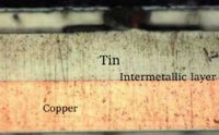
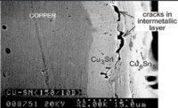
Many brass and copper connectors are tin plated, and the fine border between those two disimilar metals is closed to the outside elements. However, a strange long-term migration and intermixing of those metals occurs in that thin layer, leading to a form of intermetallic corrosion, which can also interfere with good current flow. Same can occur at the boundary of a substrate and a layer of solder, which can include boundary cracking of the solder. These types of degradation take many years to form, not an issue within normal life expectancies of typical vehicles. But, becomes real after 30 years or more.

We studied this back in the 80's, as part of determining the MTBF (Mean Time Before Failure) of various electronics products. These pictures represent similar biopsy-like micro cross-sections of tin plated copper-clad printed circuit boards.

IMC01.jpg IMC02.jpg IMC03.jpg

What all this means, is that with the age of our bikes, electrical problems can occur which defy normal diagnostic expectations. For example, you could have a failed wire connector which still shows appropriate voltage, but won't deliver current to a device, like a light bulb. This was my experience three years ago with a failed turn signal bulb. The contact at the bulb base showed voltage, but the bulb wouldn't light up. Maddening. Traced it to intermetallic corrosion within the contact face. Cleaned up the face and re-tinned it, works fine...
 
Last edited:
With this in mind, consider that no matter how good your ground connections and wiring, the 'only' place that has the 'true' ground voltage is your battery's (-) negative terminal. Everywhere else in the grounding system will have some amount of voltage, increasing as the current increases.


I don't disagree with much of what you are saying, except that your conclusion that the negative side of the battery is the lowest potential on a bike or anything with a changing system for that matter.

If the battery is providing current then yes it is lowest. However, if the battery is being charged by say an alternator, then the alternator return is the lowest. I'll ignore the details of the negative voltages on the AC being even lower and just deal with the DC return currents on the alternator.

This is more than just of acedemic interest which is why I bother to point it out. Shunt type charging systems are sensitive to dirty and corroded connections between battery and regulator. As an example 10 amps flowing and 0.1 ohms resistance would generate a 1V drop between battery and regulator. At the GS Resources we see this all the time where neglected bikes using shunt regulators and the are 0.5 and more voltage drops between battery and the regulated R/R output.

I have been a proponent for a "single point ground" as a collection point for all return currents before returning to the R/R(-). This tends to:
a.) make the ground paths much more obvious (which on a GS are pretty circuitous) and
b.) separate battery charging return currents from all of the other return currents. The only voltage drops between battery and SPG are then that due to charging currents and not all other electrical loads, making the system less susceptible to the effects of corrosion.

actually I think I already discussed most of that here.

http://www.xs650.com/forum/showthread.php?t=41965

And now I see you were the first to comment on the thread :doh:
 
Hey, posplayr, welcome back! Thanx for chiming in, and your link (couldn't find it).

Yes, you're right about the negative side of the charging system. Given that voltage drop scenario, and adding in what could happen on its positive side, then there's a pretty large voltage discrepency.

Have a look at THIS negative voltage spike:

http://www.xs650.com/forum/showthread.php?t=42605
 
Just for the sake of confusion, we tend to think that current flows out of the positive battery terminal and returns to the negative when in fact it is the opposite. The negative battery terminal is where the current flows out of the battery and returns via the positive terminal.
 
Hey, posplayr, welcome back! Thanx for chiming in, and your link (couldn't find it).

Yes, you're right about the negative side of the charging system. Given that voltage drop scenario, and adding in what could happen on its positive side, then there's a pretty large voltage discrepency.

Have a look at THIS negative voltage spike:

http://www.xs650.com/forum/showthread.php?t=42605

Thanks for the welcome back :).

I do recall a discussion about the glowing LED on but having no first hand knowledge of the XS electical could only offer a "makes sense". You schematic makes it more clear.

Adding the flyback diode to a mechanical relay coil is standard practice, adding the diode to the output of the relay would serve the same purpose to squelch the energy in the alternator coil when there is a large dI/dT.

In a more general sense, there are automotive standards to deal with load-dump which typically are +/- 100V spikes of varying durations. The very shortest 10 usec pulses are considered ESD and when they ar 10 msec or longer they are load dump. You need quite a bit of silicone to absorb the longer spikes on low impedance inputs and outputs.

As an example of you can google yourself.

http://www.ti.com/lit/an/snva681a/snva681a.pdf

Unfortunately I couldn't see any plots so do not know what the peaks or durations are for the pulse you have. For the Solid State Power Box I designed, I use 1500W TVSs to deal with load dump. Something like 25V at 60 amps for short durations.
 
Just for the sake of confusion, we tend to think that current flows out of the positive battery terminal and returns to the negative when in fact it is the opposite. The negative battery terminal is where the current flows out of the battery and returns via the positive terminal.

I think you are confusing current and electrons; they are two different things.

I'll try and add some clarity; Electrons flow from negative to positive, but current flows from positive to negative.

Electrons adhere to a fundamental principle of physics, and current adheres to an almost universal convention of electrical engineering

My comments were in regard to the discussion at hand so electron flow is pertinent. Convention simply means that an expression is accepted as is whether or not it is factual. This goes back to the earliest electrical experiments conducted by Benjamin Franklin and he got it backwards, but it remained conventional.

When Benjamin Franklin made his conjecture regarding the direction of charge flow (from the smooth wax to the rough wool), he set a precedent for electrical notation that exists to this day, despite the fact that we know electrons are the constituent units of charge, and that they are displaced from the wool to the wax—not from the wax to the wool—when those two substances are rubbed together. This is why electrons are said to have a negative charge: because Franklin assumed electric charge moved in the opposite direction that it actually does, and so objects he called "negative"(representing a deficiency of charge) actually have a surplus of electrons.
 
My comments were in regard to the discussion at hand so electron flow is pertinent. Convention simply means that an expression is accepted as is whether or not it is factual. This goes back to the earliest electrical experiments conducted by Benjamin Franklin and he got it backwards, but it remained conventional.

When Benjamin Franklin made his conjecture regarding the direction of charge flow (from the smooth wax to the rough wool), he set a precedent for electrical notation that exists to this day, despite the fact that we know electrons are the constituent units of charge, and that they are displaced from the wool to the wax—not from the wax to the wool—when those two substances are rubbed together. This is why electrons are said to have a negative charge: because Franklin assumed electric charge moved in the opposite direction that it actually does, and so objects he called “negative” (representing a deficiency of charge) actually have a surplus of electrons.

I think your statement clearly confused electron flow with current flow although I will not assume you do not know the difference. However, your post was quite accurate in regard to
Just for the sake of confusion,

Perhaps it was intentional, perhaps not but my statements stand in juxtaposition as they are clear despite the somewhat arcane relevance of electron flow v.s. current.
 
+++ to 2M's posts about grounds. I recently hand soldered a new wire harness for my 78 special and all of my malfunctions turned out to be ground related!! The new powdercoat paint contributed to some of the grief - turns out the paint is not conductive (another xs650 thread!)
Excellent thread even after a few readings.
thanks!:thumbsup:
 
I mentioned open circuits earlier. Sometimes people use the term 'short' to describe any sort of electrical failure, but that can lead you down the wrong road. A 'short' is where a wire or etc is grounded to the metal of the chassis causing electricity to take a 'shortcut' back to the battery, this generally results in fuses popping and if the fuse is replaced with something that won't blow it usually results in smoke and/or fire.

An 'open circuit' is where power is not getting to whatever you want to have work. It helps to visualize an open circuit as similar to a blown fuse: power comes into one side of the fuse but since the fuse is blown it can't get to the other side.

As before, start with a wiring diagram. To do otherwise is a sure route to madness. A simple and inexpensive tool which will help a lot is a test light.

test_light.jpg


How it's used:

tsp-550-8.gif


The alligator clip is connected to a ground, then the sharp probe is touched to whatever you need to test. It helps for the probe to be really sharp, since sometimes you need to probe into a wire through the insulation.

Referring to your wiring diagram, start with the fuse block and the ignition must be on. Touch the probe to the fuse block terminals one at a time with the fuse in place. If one terminal lights up and the other doesn't, check that fuse carefully before going any further. Remember, these old glass tube fuses will break internally and look like there is nothing whatsoever wrong with it.

If the fuse is fine, then keep checking as you go up the wiring harness. It's best to check both sides of the connectors, in most cases you will find your open circuit at one of those. As you go up, if the probe keeps lighting up that means you have power that far. When the probe no longer lights up, you are very near the source of the problem.

Let's say you have traced the problem to a connector; when it's plugged in you have power on one side but not the other. Unplug the connector and carefully examine the terminals. You will generally find something wrong, one is bent or etc. Sometimes when you disconnect the connector you will notice that the plastic is brown and has a bubbled appearance around a terminal. That's because it has been hot and started to melt the plastic. A sort of extreme example of this:

mxelbr07a_blower_resistor_Dodge.jpg


What happens is the female terminal does not tightly grip the male terminal, this adds to the resistance across the connector. Whatever the load is in that circuit is still trying to draw the amount of power it needs and the poor connection heats up, just like a stove element. As the metal terminals get hot, the female terminal loses its 'springiness' which causes it to relax its grip which in turn raises the resistance which etc etc etc. (Funny how female stuff is at the root of so much trouble, isn't it? :laugh:) The fix: replace the terminals and the plastic connector housing.

Sometimes a wire will break off at a connector. That's usually because the harness flexes at the connector. The metal wire will 'work harden' and eventually break. Once in a while this will happen inside the wiring harness, that is difficult to track down unless you open the harness up. From previous experience, sometimes it's easiest to just run another wire outside the main harness, bypass what's inside.

You don't see it much in these harnesses but automotive harnesses will have splices inside which are done with brass crimp fittings. That's normally when a wire has to go from a single power wire to a couple of different circuits. The horn/brake/turn signal wires are probably the best example of these bikes, a single wire from the fuse block has two other wires (of different colors, no less) spliced to it inside the harness. That's another reason to be sure you have a wiring diagram.

A real head scratcher sometimes is a wire with corrosion inside it. This happens when water gets into the wire, it sort of 'wicks' its way in. Copper and other metals which conduct electricity are prone to corrosion in the first place, add a little electricity to the trapped water and just watch it go. Examine the wire carefully; if you see that blue-green stuff in the wire at the connector it's like an iceberg, you are only seeing the tip of the problem. The real problem is further back in the harness. Like this:

004.jpg


Sometimes it looks like this:

wire_corrosion.jpg


In this case, the corrosion will not conduct electricity as well as real live copper wire. It may conduct a very small amount, and that's why sometimes using a multimeter instead of a test light will lead you the wrong way. It's entirely possible to check a connector with a multimeter and it shows battery voltage but your load still does not work. Why? It might be 12 volts but only 1/10 amp, which is not enough to run the load. It also won't run your test light, which is why I prefer using a test light to trace an open circuit.

Switches can be another open circuit source. The terminals can get corroded or dirty and not conduct electricity, that's usually worst on something that's been sitting a long time (like a 'ran when parked' barn find XS). In this case your test light will show power going into the switch and nothing coming out. Generally that's a case of squirting some sort of penetrant into the switch, then working it back and forth or however it goes several times, then check it again.

On old switches which carry a lot of electrical load (think ignition switch), the contacts which are made into the plastic can get hot from a high amp draw. That melts the plastic which causes the terminal to sink into the plastic and quit making contact. That may not be readily apparent, it might require some very close examination on the part of the guy checking it out.

columswitch1.jpg


This is one reason to use a relay for a big electrical load, that way it's taken off the switch and put on the relay's terminals.
So helpful, hope you're still doing this as I am just starting!
 
Back
Top