1971 Build for Dad

It has been mentioned already regarding the tail light running direct via the 20A fuse. In the past some have lost all power to their bikes because of a short in this Blue wire. This wire to the tail light sees a lot of vibration which slowly wears through the insulation. My solution was to fit a single fuse in the headlight bucket to intercept the blue wire from the ignition switch. I know it is very cramped in the bucket but the fuse fitted OK.

It seems to me the horn is wired direct to the 20A fuse??

On another forum I saw a warning about bike horns. They draw a significant current, perhaps 6 - 12A depending on the type. You may want to have the horn on its own fuse or powered from a line that does not draw a high current i.e. I would not have the horn wired on the same line as the headlight with a 10A fuse.
 
Just noticed a mistake on Jayel's original drawing. The blue/white wire coming from the Safety Relay grounds at the starter button to energize the starter solenoid. This drawing also ties it into the Eng. Stop Sw. As soon as you hit the starter sw, power from the kill sw will go straight to ground and blow the fuse. That blue/white wire does not go to the stop sw. It should go from the safety relay straight to the starter sw... and nowhere else.
Edit: Jayel's original has been fixed by Skull.
http://www.xs650.com/threads/some-wiring-diagrams.61/#post-3656


Untitled.png
 
Last edited:
All great information so far, you guys are awesome!! No surprise about the fuses, I didn't have much confidence in where I placed them... You are correct in assuming it is an late-model stator.

I would think about utilizing one of the gonzo boxes. Known to work and much easier to replace if it fails. All the Yamaha TCI boxes are at or near there 40th birthday and are analog devices that depend on RC constants to function properly. 40 years is a very long life for capacitors.
Are you planning a custom wiring loom of a prefab ?
Ok, I'll give it a shot. The old electronics are a concern for me and I already have a couple of GN250 igniters.

I plan to adapt a prefab loom for this bike. I didn't have to mess with any of the electronics on the '80, so I don't really have a good grasp on which wires run where on the bike. Dad had about all of the components for a custom harness, so I am going to use those to modify, as needed.

I lost my dad when I was very young and have been trying to locate one pf his race cars (H-Mod) for a number of years with no luck.
I hope you can track it down, those are some awesome old cars.

I will incorporate all of these changes, along with the GN250, and will post a revised copy - much appreciated.
 
The 70-71 XS1/XS1B bikes used the smaller/ narrower 5.5 ah battery, kickstart only.

The larger XS2 battery box should slip right in, holding a 12ah battery. Alternative would be to find a suitable hi-capacity Li-ion battery that would fit into the XS1 box.

Might want to look into things XS2, since it's the most compatible with things XS1, including wiring.

Mailman's XS2 thread would be a great reference...
 
Last edited:
Alternative would be to find a suitable hi-capacity Li-ion battery that would fit into the XS1 box.
This was my plan. Newer lithium cells can hold a truly astounding amount of energy. I have some for my bigger RC planes that could probably scoot the whole bike along if setup correctly.

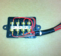
One quick question about fuse blocks... I have two available to me. One acts more like a "gang" and distributes power from a single source (the battery). The other simply interrupts a circuit, no power distribution:

upload_2021-2-5_11-57-2.png


I know my wiring diagram as it currently stands would best utilize the 4-position block on the right. However, are there any advantage to using the left block and distributing power to each system from a single source? Does it make sense to use this on a bike? Dad was planning on installing the left block so I thought it worth asking.
 
I think the best choice involves a combination of personal risk-management and diagnostic skills.

My XS1B, and the other early bikes use only 1 fuse. It provides protection for all scenarios, but any scenario blows it, and there you are. If you're good at diagnosis, and have a simple/solid/clean electrical system, not much of a problem.

Multiple fuses may allow you to *limp* home, like if something other than ignition fails. And, the separation of the systems helps with diagnostics.

Kind of a choice thing...
 
Updated Diagram

The following changes were made:

1. @Jim
a. 5A fuse added to taillight
b. Redundant fuse removed
c. Dedicated ignition fuse
i. Didn’t move position of original brown wire fuse, as it is dealt with by 1c.
d. Erroneous safety relay connection removed
2. @Paul Sutton
a. Horn power moved and fused
3. @Team Junk
a. GN250 igniter added
i. Can you confirm that the green/white wire from the pickup is just capped off?

upload_2021-2-5_12-37-0.png


Thanks again for all of the help. However, before proceeding I think I am going to play around with a design using the power distributing fuse block and see what that would look like. Either way, it would be good for me to get some more practice with vehicular wiring.
 
i. Didn’t move position of original brown wire fuse, as it is dealt with by 1c.
Follow the (current) path... from the batt to 20A fuse.... on to the iggy sw.... out the iggy on the brown wire.... to the front brake light sw..... Now, what happens if the brake light sw (or associated wiring) shorts to ground? Which fuse blows?
 
Last edited:
As for those two fuse boxes you have, I have used both. The big one, but with ten fuses, I used on the Virago because it had plenty of space for fitting. The four fuse unit I found too tall to fit under the seat of a 81 Special. Some have used a similar style four fuse version but I think it is not so high??

For the 81 Special I settled on the modern version of the original glass fuse box as used in many Yamahas from a few years back:
FuseBox.png
It does have a nice lid and very low profile in height. Here is a UK Ebay link so you can see which bikes used it:

https://www.ebay.co.uk/itm/Yamaha-F...870875?hash=item1cfadcfc9b:g:3lMAAOSwhBNfx1YM

Some people have very strong opinions about these fuse boxes but it is really in reference to 30+ year old ones where the brass clips are all failing.

To me the choice of fuse box depends on how much space you have available.
 
The way you have your horn wired, it will be hot all the time and operate (blow) even with the key off. Originally, it was powered off the brown wire coming out of the ignition switch.

As far as fuse boxes go, you can't use the one on the left with one hot wire in alone. That would make all circuits hot all the time. You need the main feed from the battery to the ignition switch fused on it's own, then the brown hot wire coming out could go to that fuse block to be split and power everything else. You need a "switched" power source feeding that fuse box.

Here's an illustration of the original Special fuse box. Main power from the battery to the ignition switch runs through it's own 20A fuse. Once the ignition switch is turned on, power flows back to the fuse box on the brown wire and is split to all the other fuses .....

050OLGl.jpg
 
Last edited:
Just to give you more options/muddy the waters.. ( :rolleyes: ).....
I used one of the 4 fuse blade type blocks and isolated one fuse for the 20A. That line went to the iggy sw and back to the fuse block to power the other 3 just like the original did. Link to comment 288.


zz.jpg
 
Your head spinning yet Rhy?

I find myself agreeing with @Jim alot. I think it must be from a lifetime of screwing around with machinery that have pointy front ends. My bike is wired the same as Jim is recommending. One thing I'm changing in my current rewiring project is I'm mounting a small 10 amp 12v circuit breaker on the blue wire from the key switch on my headlight bucket to power the headlight dip switch. The headlight is the largest load on the bike and and I try and limit the amount of wire between the headlight and the battery.

Out of all this I strongly suggest using the blade fuse setup over the old Buss glass fuse setup. A lot easier to find spares out in the wild. Most gas station convenience stores have them.
 
Your head spinning yet Rhy?
Ha! My wife, "why are you still staring at all those colored lines...?"

Which fuse blows?
The 20A, thus killing the whole bike? I’m back in elementary school getting called on… Have I mentioned I dislike electrical circuits?

To me the choice of fuse box depends on how much space you have available.
I replaced this on the ’80 and it has worked great so far. That being said, I think I have enough space for a blade-type fuse box.

Here's an illustration of the original Special fuse box.
This really helped, thank you. Gave me a better idea of the “flow” of the current.

muddy the waters..
upload_2021-2-6_1-12-25.png


It’s not cheap, but a cheap alternative to the Moto Gadget.
I like it!

Back to the diagrams…

For the inline fuse option I moved the fuse on brown wire to where @Jim told me to move it initially. I also moved the horn power back to the brown wire coming off the ignition. This is Option A.

I also made this monstrosity, partly because I wanted to figure it out, and partly because I might end up using the gang-type fuse box. The 20A fuse would be inline with the wire coming off the battery. Am I on the right path?

upload_2021-2-6_1-14-31.png
 

Attachments

  • upload_2021-2-6_1-7-12.png
    upload_2021-2-6_1-7-12.png
    238.2 KB · Views: 137
The 20A, thus killing the whole bike? I’m back in elementary school getting called on…
Correct on both counts. The 20A would blow and you'd be on foot. I used to teach this stuff, so yes... you were being called on. It's an effective way of learning. :D

Re your newest iteration... well done, you're getting there. Two niggles. You lost power to the brake sw and neutral light... add the brown wire. Second, you lost the "Park" function on the iggy sw (red arrow). Do you still want that function? If not, no worries. You're doing great. Keep it up. :smoke:

Untitled.png
 
Just noticed... headlight, meters and tail are all lit as soon as you turn the key on... you lost the on/off function. It's late... I'll look again tomorrow.
 
Back
Top