2 charging electrical questions

tkurt

XS650 Addict
Messages
102
Reaction score
1
Points
18
Location
San Diego, CA
Hi All,
I recently installed a new vr-115, homemade rectifier and digital voltmeter (connected to a brown wire in the headlight bucket).

Problem 1: My digital voltmeter reads .5V less than battery (new and fully charged). Is this too much of a drop? I would suspect the ignition switch, but can't actually find one. The individual wiring connections have zero resistance.

Problem 2: If I do the feeler gauge "slap test" I only get weak magnetism at the rotor, and my positive brush only measures 10.7V with the bike on. The resistance of the rotor measures 5ohms between rings and infinity between either ring to ground.

I started tracing connections back from the brushes, and found that I lose a little over 1V from the brown wire TO the regulator and the green coming FROM the regulator. My guess is my regulator is shot (I think I may have shorted it when installing), but was hoping for confirmation before I buy a new one. Any thoughts?

Thanks!
 
1. The voltmeter is reading the brown wire voltage, not the battery voltage, so a drop of .5 Volt is normal and probably is a drop across the ignition switch, fuse etc.

2. There is a drop of at least 1.2 volts across the transistor in the Voltage regulator, so 10.7 is about right at the brush.

Not sure I understand the last bit, but it is probably the same as #2.

There are voltage drops when the current passes through any and all of the various connections, switches, contacts and transistors, so that is why it is important to keep all the connections clean. Even the fuse will develop a drop of .25 Volt, switch contacts up to .5 Volt when current is flowing through them, especially when you have the headlight on.
 
Last edited:
Most of the regulators have a warranty, mine came with a one year free replacement. Might want to check on yours.
Leo
 
Thanks for the help. I just fired it up, and I don't see an increase in voltage at the battery when I rev the engine, so I think something with the charging isn't working.

[Edit]: also do not get an increase when I jump the battery positive to the green brush (bypassing the regulator), so maybe its the stator. I'll check that and let you know what happens.
 
Last edited:
Thanks for the help. I just fired it up, and I don't see an increase in voltage at the battery when I rev the engine, so I think something with the charging isn't working.

[Edit]: also do not get an increase when I jump the battery positive to the green brush (bypassing the regulator), so maybe its the stator. I'll check that and let you know what happens.

You could measure the AC voltage across any 2 of the white wires that come out of the alternator (check all 3 combinations). You can measure at the multi-pin connector with all connections normal, and the engine idling. Should have 12.5 to 13.0 volts AC.
 
With no increase by jumping the brush it is probably the rotor, much more often the problem.
Both are easy to check. rotor, just check the ohms slip ring to slip ring and slip ring to ground, stator from white wire to white wire, three pair, With the yellow wire to the safety relay unplugged, and from any wire to ground.
Any of these tests to ground should show infinity. Rotor 5 ohms, stator .9 ohms.
Leo
 
Hi guys,

With the bike idling and the yellow safety relay unplugged, I get 10 AC volts across either of 2 pairs of the white wires from the generator. The third white wire is really low - like 2-3 volts when connected to either of the others.

With the bike off and looking at resistance, I get infinity from the white wires to ground, but not the green wire - it only measures about 1 ohm. So, do I have short somewhere?

Thanks again for your help, I am learning a ton.
 
Bike off, connector unplugged, ohm between the white wires, 2 at a time, what do you get?
 
Hi gggGary,

I get infinity between any of the two white wires, or any of them to ground. However, blue to ground is ~1-2ohms and green to ground is about 6ohms. I'm not sure what this means at this point, so I appreciate the help.

-t
 
Somethings not good there, the red and green wires are the brushes, the the blue wire is the neutral switch, ignore them. any two white to white should show about .5 ohm . A few times I have found broken white wires in the bundle around the sprocket area.

The guide covers this stuff pretty well http://www.xs650.com/forum/showthread.php?t=10561

I had the safety relay disconnected, sorry for the confusion! So, with the yellow wire connected, I get about .5ohm between any combination of white wires.
 
The yellow wire shouldn't matter for white to white tests, the test for infinity to ground is done with the yellow wire disconnected. I think yellow to any white shows about .5 ohms.
But if the white to white tests are good your stator should be OK.
Show us a couple of pics? Amazing what we notice sometimes when we actually see the bike!
 
On the 77 if stock should not have a red wire at the brushes. A green and black wires. The green is power from the regulator. power flows from the reg on the green, through the brush into the rotor, out the other brush where it goes to ground on the stator through the three mount screws for the brush. It also goes to ground through the black wire to the harness ground.
If you AC voltage test had two sets of the white wires producing 10 VAC and the other just a few VAC then your stator has problems.
Check the white wires for damage. A bad connection may be all it is.
When checking the stator ohms, the yellow won't matter much except when testing from the white wires to ground. When testing this you should get an infinity reading. The yellow wire goes to the safety relay where it trips the relay when the engine is running. The relay has an ohm reading of about 20 ohms. So during the white wire to ground you might get a 20 ohm reading. If so unplug the yellow wire.
When testing the white wires number them 1, 2 and 3. test from 1-2, 2-3, 1-3, This should give you a .9 ohm reading on all three pairs.
When you do the test for AC volts, test the same way.
Leo
 
Hi guys,

With the bike idling and the yellow safety relay unplugged, I get 10 AC volts across either of 2 pairs of the white wires from the generator. The third white wire is really low - like 2-3 volts when connected to either of the others.

With the bike off and looking at resistance, I get infinity from the white wires to ground, but not the green wire - it only measures about 1 ohm. So, do I have short somewhere?

Thanks again for your help, I am learning a ton.

Its difficult to accurately measure resistance of the stator windings, because their normal resistance is so low. Your VOM meter probes/lead's resistance can vary from 0.0 to 0.7 ohms. Touch your meter probes together and see what they read. Analog meters had a zeroing control, but digital meters don't have that.

If you had meter leads that read 0.0 ohms when connected together, then the white to white ohm readings should be around 0.9 ohms.

The 2 to 3 volts AC reading indicates a ground on one phase of your stator windings. Time to buy a new stator or a PMA.

The old stock stators only last so long. I believe the stator in my bike is original, which is amazing, considering the heat and vibration that these alternators must endure. I use standoffs, on my alternator cover, to allow extra cooling air to my stator and rotor. I fully expect my stator and/or rotor to fail any day now, but I've been thinking that for 7 years now:shrug:.
 
On the 77 if stock should not have a red wire at the brushes. A green and black wires. The green is power from the regulator. power flows from the reg on the green, through the brush into the rotor, out the other brush where it goes to ground on the stator through the three mount screws for the brush. It also goes to ground through the black wire to the harness ground.
If you AC voltage test had two sets of the white wires producing 10 VAC and the other just a few VAC then your stator has problems.
Check the white wires for damage. A bad connection may be all it is.
When checking the stator ohms, the yellow won't matter much except when testing from the white wires to ground. When testing this you should get an infinity reading. The yellow wire goes to the safety relay where it trips the relay when the engine is running. The relay has an ohm reading of about 20 ohms. So during the white wire to ground you might get a 20 ohm reading. If so unplug the yellow wire.
When testing the white wires number them 1, 2 and 3. test from 1-2, 2-3, 1-3, This should give you a .9 ohm reading on all three pairs.
When you do the test for AC volts, test the same way.
Leo

Hi Leo,
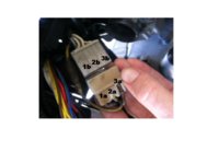
I hope my attached picture helps this description. As you say, I get 20ohms between any of the white wires to grounds, and .5ohms (but not .9) between each white pair (1a-2a, 1a-3a, 2a-3a in the picture).

When I test AC volts with the bike idling is where it gets strange.
From 1a to 2b or 3b: 0V
From 2a to 1b: 15V
From 2a to 2b: 11.5-12V
From 3a to 1b: 15V
From 3a to 2b: 11.5-12V
From 1a-1b, 2a-2b, or 3a-3b: 0V
Yesterday the ones reading 11.5-12 were closer to 10.5, so I'm not sure if something changed in the way I'm doing this or if my VOM is a little off.

This connector is crumbling apart and definitely needs to be replaced! I will probably do the whole harness at some point, but I'm still building confidence and getting tools.
Thanks again for your help.
 

Attachments

  • stator connector.jpg
    stator connector.jpg
    33.4 KB · Views: 58
Just another not, I don't think I mentioned - the battery I replaced this past week was only a year old, which is why I started hunting down charging issues in the first place. I was thinking something must have caused its early demise...
 
Hi Leo,
I hope my attached picture helps this description. As you say, I get 20ohms between any of the white wires to grounds, and .5ohms (but not .9) between each white pair (1a-2a, 1a-3a, 2a-3a in the picture).

When I test AC volts with the bike idling is where it gets strange.
From 1a to 2b or 3b: 0V
From 2a to 1b: 15V
From 2a to 2b: 11.5-12V
From 3a to 1b: 15V
From 3a to 2b: 11.5-12V
From 1a-1b, 2a-2b, or 3a-3b: 0V
Yesterday the ones reading 11.5-12 were closer to 10.5, so I'm not sure if something changed in the way I'm doing this or if my VOM is a little off.

This connector is crumbling apart and definitely needs to be replaced! I will probably do the whole harness at some point, but I'm still building confidence and getting tools.
Thanks again for your help.

Are you measuring voltage with the connector dis-connected? You only want to measure voltage with the 2 connectors joined, so that the alternator has a load. Measure the voltage by sticking the probes into the back of the connector.
 
Are you measuring voltage with the connector dis-connected? You only want to measure voltage with the 2 connectors joined, so that the alternator has a load. Measure the voltage by sticking the probes into the back of the connector.

Hi Retiredgent,
Those AC voltage readings were with the connector joined. The resistance measurements were with it disconnected.
-t
 
From your AC voltage readings, it would seem that some of the connector pins are not conducting current.

1a to 2b or 3b: cannot be 0 volts

2a to 2b: cannot be 11.5 to 12 volts (you also say 2a to 2b is 0 volts??)

That connector is bad, so no point in doing anymore testing until you replace that connector.

Thanks again for your patience. Sorry if I didn't respond specifically to each suggestion, I have read each of them and tried to do what I can.

In reponse to Retiredgentleman's posts, I agree regarding the variance in digital voltmeter readings at low resistance.

And yes, the connector is in rough shape.

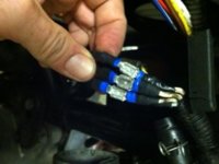
I did a temporary re-wiring of the connector, with each connection separate, to again see what I would get in AC volts across the white wires if this piece was eliminated. So in the picture, there are 3 white wires from the stator - a voltmeter between #2 (middle) and #3rd (far right) measures about 10 ACV. But anything involving #1 (left) measures close to zero. I think this must be a bad stator wire.
 

Attachments

  • stator re-wire.jpg
    stator re-wire.jpg
    13.7 KB · Views: 38
Back
Top