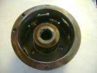
Bike stalls at stop lights? Carb or electrical?

Joe, those reading's are good IF your testing white to white to white. Check from white to the case it sit's in, that should not have ANY continuity. I have tested them before with houshold current(115 ac). One lead one the white's, the other to the case. I was shown this by a guy who has a rebuilder's shop. He said that once in a while, when the stater is questionable, that's how he would test them because the high voltage would search out any flaw's.

House current isn't high voltage, it's high amperage.

I recommend against doing this. These circuits are not rated at 15-20 amps. The magic smoke will get out.
 
You will only let the smoke out of the wire's if there is a problem. Otherwise, an open circut is an open circut. I use a small, 2 wire extension cord. Cut off the female end, make one line shorter than the other, put on a female connector ( to attach to each white wire (one at a time) and a male on the other wire. Plug it in and touch the case, a good stator wil not spark. Switch the female to each of the white wire's, unplugging from the wall when moving the connection.
Like I said, I only do this if the stator is questionable.
If you are going to go the PMA route, don't bother, 'cause all this gets replaced anyway.
 
Again, I highly recommend against doing that. There's no reason to 'test' anything with a current that will smoke your wiring or electrocute you. YMMV.

There's no reason to test for a 'spark'.. an ohmmeter has a digital readout that will show you the resistance and that's the correct test.
 
Gordon, I'm a little scared to test the stator plugging in into the wall. Is there anyway to test or anything else that I can do? I've been battling this for 2 weeks and it's killing me. Should I worry about testing the yellow wire even though it's just capped off?
 
I understand the 110v idea but s8j is smart to be reluctant to use it. The stock diagram shows the yellow as grounded. It is grounded through the relay coil. A lot of 3 phase bike stators do not ground the central "y" point so I don't think a grounded yellow makes a difference either way. The only difference it makes is that you need to know that there are no shorts in the windings of the stator and that is hard to determine if the yellow is grounded out somewhere. As someone else has mentioned shorted/broken wiring in the leads running through the rear sprocket area happen. That was the issue on one otherwise good stator I had.
 
Last edited:
As GGGary stated, you allready said you took the reading's of the white wires, and then to the cover. I only mentioned the 115 volt test for use only on a questionable stator. I think you said you thought your stator is not shorted to the case. On Bikernet .com, you could look at the schematic for the charging system and go from there. The resistance on the three white's should be at .1-.5, and the rotor should be 5.5-6.0. The reason for the schematic is to check ALL your connector's physically, not just eyeball. Take them out of the holder's and look where they are crimped to the wire. This is a common area for problem's. And, like Gary said, the wiring where it goe's by the chain get's very brittle and intermitent problem's could be right there. I remember your saying that there is minimal electric's, and I am pressumeing your using just the stock wiring for the charging system. The rectifier/regulator has to be grounded, real good, as this is what regulates the system. It could be that the battery is too small for this system, and caused the rgulator to now test good, but give false signals. I had one that did just that, would charge, then be stuck at the side of the road. Thats when I got one of those Kuriyakin LED voltmeter's. It showed me that it would be charging, then, for no reason, start going crazy, up, down, flat, overcharge, ect. I was lucky to have a couple of regulator assy., and put in another, and all was good after that. I think my regulator went bad because of a bad engine ground. Burned up 3 rotor's, and I think thats what did it.
 
I just started to do Curly's test today and he's where I'm at so far. Keep in mind that I charge to 14.5 without lights on.

1. Battery 12.6
2. passed with the feeler gauge test.
3. Jumped to ground--- Nothing
4.Voltage at battery 12.57. Voltage at Brown Brush 12.22
5. 5.9 ohm between(should be 5 to 5.5) and infinity from slip rings to engine.

I somehow managed to strip out the brush bolt and I'm going to the hardware store to get another one. Hopefully I didn't strip out the brushholder too.
I also checked dc voltage(I know I should have checked AC) at the white wires and I found an inconsistency in the results. I was getting 7.8 on two whites and 11.7 on the third. Any idea what this means and if it relates to my hassles?


I retapped the brush holder and got everything back up and running. Here's the last of the charging system test:

6. I should have been getting around 10.5 and 11 AC volts between each white wire. My readings were lower
Between 1 and 2= 7 volts, 1 and 3=8 volts and 2 and 3=7.5 volts
7. Test results should be between .4 and .5 ohms and my findings were pretty close. I got .6,.5 and.4 ohms.

Test 7 also says that
"If the readings are now good then the yellow wire or safety relay are shorted. If there is one or more that still read low after disconnecting the yellow then check those legs by touching one lead to ground with the other on the white wire. You should see a very high Kilo ohm or infinite reading. If you get a low resistance check the stator lead pigtail to see if it is pinched by the cases or rubbed through on the frame. If that looks ok then your stator is shorted and needs to be replaced. "

I assume that since my yellow wire is unplugged and capped of I have a short somewhere in the yellow wire? Is there something I'm missing? I believe I followed everything correctly.

Gordon, Not sure if you have seen all the results from Curly's test because this test is getting pretty long. I'm not using stock wiring for the charging system. I got rid of all the block connectors and soldered everything together. I had to cut it apart to measure resistance between the white wires. I'm gave up trouble shooting with the small battery. I have a brand new tractor battery hooked up using the small battery grounds. i will try to find the heavy original thick ground and see if that help any. I will also remove the rest of the stator wires from behind the front sprocket and cut it out of the shrink wrap and check the wires.
 
Last edited:
Joe, instead of cutting open that shrink tube, if any of the white's are exposed at the stator end, use a small saftey pin to pierce each wire. And the same at the other end. Might save some un-nessisary work. Try the ground wire also.We will get this sumbitch yet!!!
 
I'm checking for resistance right? I'll give it a try. May not be able to til tomorrow. So I assume you think my charging components are working properly? I found my original ground wire but it's only like 5 inches long. Not sure if thats gonna work the way my bike is set up now. I'll try and figure something out with the ground wire.
Thanks again for all the help everyone!!
 
My girlfriends off today so I can't really work on the bike too much. I had a few minutes so I went outside for a quick test. I took the stator off but I'm not sure I'm testing properly. I installed butt connectors the other day after I cut my wires connecting my stator to the regulator. I pierced one white at the stator base and I checked for resistance to each white butt connector. I'm getting the same readings as yesterday when I tested resistance between all three whites. .5,.5 and I think I got a .7 but the pin seemed like it was loosing connection. I really needed a second set of hands. Did I perform the correct test? If I'm doing this correctly I'll test the other two whites at the stator base.
 
Joe, sound's like your stator is ok. You did your rotor before, right? Got like 5.8 ohms. and nothing (infinity) to the center. If you happen the have a junk jump box around, those cables are long enough and have nice small fitting's. Could be that the small battery you got was no good to begin with. We will see with the tractor battery, right?
 
Am I performing the set you suggested properly? Do you think my charging components are ok? I'm going to check for a short in the whites later today.
 
My rotor was around 5.9 ohms Ill check it again later since the stator is off the bike. I'm worried about that and the fact that my ac volts are were low coming from the white's at the stator. If you look up a few post you will see all my charging test results.
 
Well I spent another night in the garage messing with this damn thing. All my wires are ok on the stator. All of my grounds are ok too. I'm still only getting 7 to 8 ac volts coming from the stator. I don't know what else to do, I think I'm just gonna say screw it and gather parts for the PMA swap. I do appreciate everyones time and patience trying to trouble shoot this problem!
 
Some one had posted a link for a PMA,somewhere here. And, the whole thing was like $400. Alot of ching, but everything was new, and has a warrenty.
 
A new stator is like $200, Hughes pma's are now $320 for the whole thing. I figure I can sell some of my working components to offset the cost.
 
The Hughes PMA, is that the one thats the whole kit? Just FYI, the pma set-up is ancient, Just remember how long lawn mower's have been around. Sometime's, the old design's are better than the new stuff, more reliable. And they took a beating.
 
The XS650 stock alternator is really a weak design. The 'rotor' is both a field coil and rotor built in, and it compromises the effect of the magnetic field on the stator coils.

The most effective alternator setups have no brushes at all, like the Honda cb750 which has a field coil which has mechanical force applied to the field by means of a simple ferrous metal rotor. No perm magnets, and it's very efficient.

A well designed alternator is much more efficient than a non rare-earth magnet PMA, since the magnetic field will be much stronger.

Here's what I am talking about :

The mechanical rotor fits into the alternator cover that holds both coils, no contacts, and no brushes and no moving parts with wires on then.

The downside of course is that this system weighs about 10 lbs more.
 

Attachments

  • DSC07828.JPG
    DSC07828.JPG
    133.5 KB · Views: 88
  • cb750_alternator.jpg
    cb750_alternator.jpg
    70.3 KB · Views: 88
Last edited:
Back
Top