can somebody verify my wiring?

Snikare

XS650 Addict
Messages
128
Reaction score
2
Points
18
Location
SFBay
I have rewired a custom electrical set up on my bike and I need someone that can verify what I have done. I've put it all together and tried testing the bike by looking for a spark in the plugs but I have not been fruitful.

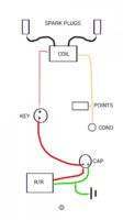
I've installed a HHB PMA, to a regulator/rectifier. The green wire connects to the negative side of a Sparxs capacitor and is connected to ground. The red wire is connected to the positive side of the Sparxs unit and then goes onto the battery post of the key. From the IGN post of the key the wire ruins to the end of the coil.

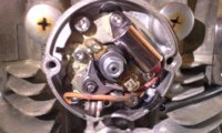
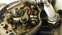
I'm running a single set of points and a dual lobe with a single condenser. That leads to the other side of the coil.

I'll be wiring in the lights after I get things running.
Thanks for the help. I
 

Attachments

  • Screenshot_2015-01-11-22-52-20.jpg
    Screenshot_2015-01-11-22-52-20.jpg
    57.5 KB · Views: 93
Here is the best diagram out there with all the setups. By your diagram are the points grounded? You don't need REG/REC to fire up bike to test with a battery but if you are running SPRAX it has to be inline . I would use a battery first to get it fired up and get a charge in the ALT first. Some guys have had problems with just trying to kick it without a jump from a battery. Use the battery to get it running then disconnect it and run it just threw the SPRAX then kill motor and restart if fires up all good.
 

Attachments

  • 650 wires.jpg
    650 wires.jpg
    94.1 KB · Views: 88
I think I might hook a battery up to the system in place of the cap to make sure the Pma is working correctly and the bike starts just to make sure there are no other problems.
 
Hooking up a momentary battery is a good idea. But theoretically the diagram I drew should be fine right?
And the points are grounded just by virtue of being mounted to the head...?

Thanks for the input.
 
here's what my points look like. I'll get more pictures of the rest of the wiring later today.
 

Attachments

  • 20140322_112256.jpg
    20140322_112256.jpg
    181.1 KB · Views: 69
Good catch eagle eye! But it seems to be fine if you look at it from another angle. Wouldn't those be connected to ground anyway through just by being screwed onto the head...?
 

Attachments

  • 20150112_170804.jpg
    20150112_170804.jpg
    153.3 KB · Views: 63
Last edited:
Are there any glaring deficiencies in the diagram I drew? I'm not positive about the way the coil is set up. It seems like I am missing something either there or at the points...
 
Last edited:
... Wouldn't those be connected to ground anyway through just by being screwed onto the head...?

The lead from the coil, lead from the condenser, the little points bolt they attach to, the points spring, and the points moving arm all attach together electrically and shouldn't touch ground anywhere except for the grounding contact of the points body.

You can rotate the engine so that the points are open, and test for zero connectivity to ground at that little points bolt. Then, from that little bolt, ensure good connectivity to the moving points arm, and to the coil.

Then rotate so points are closed, same test, and ensure that connectivity to ground is good, else clean the points contact faces...
 
Oh wow. My points were way out of alignment. I'll get that fixed and continue with checks. I can't believe I overlooked that.
 
Back
Top