Digital Gear Indicator for the XS650

Lemme know if you work it out Paul - that really could be useful!

Certainly, the "headlight blown" indicator is not....

Pete
 
The difficulty is to distinguish between 1st and 2nd. In the dream world I would put a pressure sensor on top of the gear lever and another on the bottom so I could count up and down. The reality may be a little mechanical counter taped to the handlebar that I press each time I change gears then mentally divide by some factor...... I got the answer, an Abicus with five green beads!
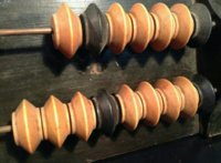
 
Tried that - but the 650s vibrations kept moving the darned beads around and I kept loosing count.
 
With changing up the key is to only activate the light when an up signal from the gear lever follows a voltage low from the neutral switch. I think that is right - the switch goes low when it grounds the lamp to complete the circuit to earth. Unfortunately I do not see how to predict the approach from 3rd to 2nd. This is probably why the system TwoMany is reviewing is interesting because if set up well it will count up and down as long as each up/down is a definite gear change - hence the need to precisely locate the sensors.

Interesting Puzzle!
 
I find there are only two gears in my gearbox; the right gear and the wrong gear.
A gear indicator would be a simple light to show when the bike was in the right gear!
 
...In the dream world I would put a pressure sensor on top of the gear lever and another on the bottom so I could count up and down. The reality may be a little mechanical counter taped to the handlebar that I press each time I change gears then mentally divide by some factor...... I got the answer, an Abicus with five green beads!

Abicus??? How ' bout the stringed bead scorekeeper found in poolhalls?
BeadScore.jpg
 
This is the direction I'm taking for the shifter sensor.
I plan to mount a self-centering on-off-on momentary toggle switch to the bottom of the shiftshaft guard. Its toggle lever will be actuated by a protrusion on the shaft.
ShiftShieldMod1.jpg


Carelessly and recklessly cut off about 10mm of the bottom cover.
ShiftShieldMod2.jpg


Again with the careless and reckless, grind some extra clearance for a clamp band.
ShiftShieldMod3.jpg


And now, stare intently, stumped on whut to do next.
ShiftShieldMod4.jpg


The idea is to have some sort of fork, u-notch, fingers, whatever, that'll nudge the microswitch fore-and-aft, just the right amount...
 
OK - looks good but wouldn't something like a Hall effect non-contact sensor be more robust in a wet/dirty environment than a little mechanical micro-switch (I don't know for sure - I'm not an electrical guy).

Those are the sort of sensors used on cruise controls - just a little magnet glued onto the drive shaft.
 
First, I'd like to apologize for the crude graphics, this was done with the Windows Paint program ( I couldn't find my crayons....).
Here's my suggestion on the shift indicator implementation. NOTE: This would only work if there is at least a 1/4'' space between the left engine case and the shift shaft sprocket/chain guard. Not sure if that space exists.
This "design" would house the sensors inside the cover, giving some weather protection and hiding the whole thing from view. Would probably need some sort of protection from the oil being slung of the chain though. It would consist of a slotted sensor mounting plate with a hole in it that is slightly larger that the shifter boss inside the cover, and a cinch bolt to hold it in alignment. The sensors would mount to this at the correct working angles. Almost touching it would be the (also aluminum?) magnet holder that mounts directly on the shifter shaft. Alignment could done by using one of the case mounting holes as a reference.
I've never used one, but it looks like the gear indicator kits on eBay would be really hard to beat, dollar for dollar. You get the indicator, logic, wiring, and sensors for a song.
Example:
http://www.ebay.com/itm/LED-Digital...e560049&pid=100005&rk=3&rkt=6&sd=380727791188


Just my two cents.
inside cover.JPG
pickups and display.jpg
 
Micro switches next to the shift arm like you would do with a quick shifter, just have them adjusted precisely otherwise a missed shift, or the search for sixth, will cause the count to be off. Otherwise you would think the functionality of it should be pretty easy to accomplish. Making it look good is another question entirely though.
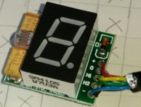
 
Good thinking there, guys. It'd be great if others would take the challenge. I certainly don't have the resources to make this a top-notch implementation. Just flailing away with destructive, spark-producing tools.

OK - looks good but wouldn't something like a Hall effect non-contact sensor be more robust in a wet/dirty environment than a little mechanical micro-switch (I don't know for sure - I'm not an electrical guy).

Those are the sort of sensors used on cruise controls - just a little magnet glued onto the drive shaft.

Pete, yes, considered those, and have a few to play with (for a different project). Used magnet-triggered contraptions on other car projects, but just for rpms. I wanted to avoid magnets this time, for 3 reasons:

1- Don't want things getting attracted to and sticking to the magnet. Leave that for the drainplugs.

2- This current design concept uses the shift shaft, which will not only rotate +/- 11°, but will also move in/out of the case a millimeter or 2, which could influence any delicate proximity settings.

3- Using a simple switch makes this a 2-wire implementation (grounded middle post).

First, I'd like to apologize for the crude graphics, this was done with the Windows Paint program ( I couldn't find my crayons....).
Here's my suggestion on the shift indicator implementation. NOTE: This would only work if there is at least a 1/4'' space between the left engine case and the shift shaft sprocket/chain guard. Not sure if that space exists.

Hey, resto! Welcome to the party. Your graphics are fine, gets the idea across. On my '71, the shiftshaft guard spans all the way across to the sidecover, and touches it. I have to press-in on the guard a bit when reinstalling it, so that it doesn't prevent my sidecover from fully seating. That's why I had to cut out that 10mm piece from the end.

This "design" would house the sensors inside the cover, giving some weather protection and hiding the whole thing from view. Would probably need some sort of protection from the oil being slung of the chain though. It would consist of a slotted sensor mounting plate with a hole in it that is slightly larger that the shifter boss inside the cover, and a cinch bolt to hold it in alignment. The sensors would mount to this at the correct working angles. Almost touching it would be the (also aluminum?) magnet holder that mounts directly on the shifter shaft. Alignment could done by using one of the case mounting holes as a reference.

The clamp arm you show there is something I'd like to find. Probably will have to fabricate the thing.

I've never used one, but it looks like the gear indicator kits on eBay would be really hard to beat, dollar for dollar. You get the indicator, logic, wiring, and sensors for a song.

Yessir, that's the one we're going to modify here.
Hang on to yer panties...
 
Last edited:
Modifying the gear indicator gadget.

This particular first mod would probably be unnecessary for most folk.
I don't recommend doing this, it just adds a lotta work.
It simply removes the original large LED digit, to allow for wiring a remote display.

The original circuit with LED.
GearIndicatorGuts01.jpg

I used a dremel cut-off wheel to carefully cut each leg of the LED.
Then simply unsoldered each leg stump from the board.
GearIndicatorMod01.jpg


I used a 9-conductor computer data cable to extend the connections.
The original LED legs are the 10 holes, 5 across the top, 5 across the bottom.

You have to map-out each pin on the new LED to match the old LED. This will be different for whatever LED is chosen. Just keep track of the wire colors. The replacement LED needs to be Common-Anode, since the power is common/shared, and each individual segment gets grounded.
 
Last edited:
The second mod serves 2 purposes. It removes the gliches from the sensors, and limits the gear count to "5".

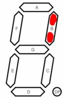
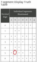
If you study this pic of the 7-segment LED layout, and the following truth table, you'll notice that "Segment b" is illuminated for numbers 0 (neutral), 1, 2, 3, and 4.
Segment-b.jpg 7-SegTruthTable02.jpg

When a number "5" is illuminated, that "Segment b" is turned off.
We'll use the drive signal for Segment b to prohibit detection of upshift signals after number "5" is reached.
 
The 2 shift sensor inputs to the circuit board go thru the two bottom mini-diodes, D4 and D7, in this pic.
GearIndicatorGuts02.jpg


We're going to remove those 2 little diodes, and replace them with the debouncing circuitry. If keeping the original LED display, it would be best to nip-off its 10 protruding legs. They just get in the way.
 
You can simply slide an Xacto knife point under one of the surface-mounted diodes, and slowly twist/lift the blade while applying soldering iron heat alternately to each end of a diode. Here, diode D4 (for the UpShift signal) has been removed.
GearIndicatorMod02.jpg


Here, diode D7 (for the DownShift signal) has been removed.
GearIndicatorMod03.jpg
 
Back
Top