Help identifying rectifier

DevonDel

XS650 Member
Messages
26
Reaction score
0
Points
1
Location
North Devon, UK
Hello all I'm the new proud owner of a 1978/79 XS, which has been converted to a flat tracker.

I'm trying to make sense of the wiring and confused already (8 hours into ownership!).

Can anyone identify this rectifier (and I assume combined regulator)?

It has 3 white wires - I assume from the alternator
1 red - I assume +
1 black - negative -
1 green - I have no idea
1 brown - even less idea :wtf:
 

Attachments

  • image.jpg
    image.jpg
    207.2 KB · Views: 180
Last edited:
OK, I think I have it.

This must be a rectifier combined regulator.

I think the 3 whites are from the stator
The red is a constant +
The black is negative
The green is one side of the bushes
The brown is the other side of the bushes and a switched +

Correct me if I'm wrong?
 
Yep! i know the feeling, i never understand why these people tamper with the looms and then don't record on paper what they have done, i have completely replaced the whole of my electrics from front to back because they were so badly cut to pieces.
 
Last edited:
Hi Del and welcome,
been many years since I honeymooned in Devon on my Gold Flash/Garrard sidecar outfit.
Now that you've managed to post a photo of your reg/rect, how about posting a photo or two of the complete machine?
It may not be the complete disaster you think it is.
Also, it would streamline the Q & As if you could add a signature line to your posts that says what year and condition XS650 you have, rather than having to type that information into each and every post you make.
 
Just a teaser shot at the moment, as it is in a state of dismantlement at the moment and not looking its best.
 

Attachments

  • 12814233_10154025288511779_1685189824583429018_n.jpg
    12814233_10154025288511779_1685189824583429018_n.jpg
    60.4 KB · Views: 139
It does look like your PO did a methodical job on the wiring. Clearly labeled everything. As you said, too bad he didn't give you a list of what the labels mean.
I recommend to people that they match the new wires to the old by color. That makes troubleshooting easier. Most know that a blue wire is lighting, brown is power to most of the bike, and so on. If someone rewires with different colors they ask what the brown wire goes to and most replies are to the factory color scheme.
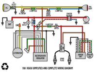
In your case this doesn't help much. What I can suggest is to start at the battery positive and trace the wires and make a diagram of where each wire goes. With your labels that shouldn't be hard.
You might want to write each system down separately. As in the charging system as one diagram, the ignition as one, the lighting as one. This might help with troubleshooting.
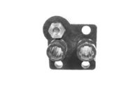
On your reg/rec I agree, it looks to be a combined unit. The description of the way it's wired is right for the 80 up bikes. The ones that came with a combo reg/rec. Your bike being a 78 or79, then it came with the separate reg and rec. They are wired differently at the brushes. The 70-79 bikes used a grounded brush and the green wire sent power from the reg. The 80 up used a brown wire to power one brush and this power went back to the reg/rec where it controlled the ground.
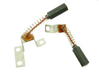
The earely brushes had one brush with a long mount strap that went from one screw up over the brush down to a second screw and went sideways to a third screw. The brush grounded to the stator housing through these three screws as well as on the black wire back to the harness.
The later brushes mounted the same. both just a short strap that came from under a screw and up over the brush.
Look under the alternator cover, the round one on the left side. Look at the brushes. See if they both use short straps or one has a long strap.
I'll post pics.
The early can be used with a late reg/rec by replacing the three steel screws that hold the grounded brush in with three nylon screws and running a brown power wire to the black wire. It's describe in more clarity in the threads describing the three screw mod.
These pics are the early brushes, holders and a pic of the early stator. It shows which three screws get changed. You can see that the wires that come out of the stator both hook in close to where the come out. The green to the lower screw, the black to the upper screw.
Leo
 

Attachments

  • 24-2650.jpg
    24-2650.jpg
    8.3 KB · Views: 120
  • 24-7079.jpg
    24-7079.jpg
    15 KB · Views: 119
  • nylonscrews2.jpg
    nylonscrews2.jpg
    46.7 KB · Views: 131
These pics are of the later brushes.
You can see the longer satrap on the early brushes where the later are the same.
The brush holder looks different where it has two insulated nuts where the early has just one.
The stator pic shows how the green wire come out and hooks to the lower screws, same as early but the brown wire comes out further and hooks onto the top far screw.
Knowing which setup you have will determine what reg/rec can be used.
The aftermarket makes reg/rec's that can work with either set up. with proper wiring either can be used.
If your bike will start and run, test the battery voltage. If it is charging then that reg/rec is wired right. around 12 -13 volts at idle, slowly rev it up and about 2000-2500 rpms it should come up to around 14 to 14.5 volts, rev higher it should not go any higher.
Leo
 

Attachments

  • untitled.png
    untitled.png
    183.9 KB · Views: 137
  • 24-8084.jpg
    24-8084.jpg
    14 KB · Views: 116
  • 80 up brushes.jpg
    80 up brushes.jpg
    2.9 KB · Views: 200
Leo, you sound like a man in the know.

I've removed the cover and this is what I see (see attached picture). Clearly the brushes have been mounted on nylon screws.

I wired it today the same as this diagram (see attached) and it just blows the 20 amp fuse from the constant + to the red in on the reg/rec.

Thank you in advance for any advice.
 

Attachments

  • Screen Shot 2016-03-28 at 14.33.19.png
    Screen Shot 2016-03-28 at 14.33.19.png
    253.2 KB · Views: 151
  • IMG_20160328_154634.jpg
    IMG_20160328_154634.jpg
    194.2 KB · Views: 147
Update.

I just removed brushes from the wiring block (FYI they are black and green so there 70-79) clearly the system will not charge but at least now the main fuse doesn't blow when i switch it on.

I then tentatively kicked it over (then vigorously) and boom started right up. Main fuse good all power to the lights etc all good.

OK so I'm looking suspiciously at the brushes/regulator side of the rec/reg is to blame here. As you can see from my previous posts the brushes have nylon screws, what is that actually supposed to do? I ask as testing the wires because both wires ground out to the frame. (Show nearly no resistance to ground).

Thanks in advance for any advice.
 
You have to understand how the two versions of this charging system work. From my understanding, the early system ('79 and older) grounds one of the brushes (upper screw, inner brush) through it's mount and the black wire attached to it, sort of a double ground. The regulator connects to the lower screw/outer brush with a green wire and switches the power to it on and off. That's how it "regulates" the charging output.

The later set-up ('80 and newer) wires the brushes differently. Neither are grounded through their mounts. The inner gets switched power fed to it by the brown wire directly from the harness. The outer is fed a ground from the regulator. This different style regulator switches that ground on and off and that's how it controls charging output.

It seems that your P.O. started on the 3 nylon screw mod but didn't complete the wiring portion of it. The 3 nylon screws unground that brush from the mount but you still have the black wire to deal with. That brush's original black ground wire needs to be clipped and connected to a switched power wire somewhere in the harness now. The green wire from your regulator will go to the other brush. It is the ground switching wire.
 
Unfortunately, that could indicate a fried reg/rec. I guess another possibility is the P.O. did the nylon screw thing when he didn't need to. Those aftermarket reg/rec units come in both versions, with either early or late style regulators. Did this set-up ever work right for you or was it bad when you got the bike?
 
I ran a diode test on the rectifier side and the diodes are all good.

I'm still confused what the nylon screws do and how I can test if they are doing what they are supposed to. At the moment they aren't insulating the brush wires from the ground.

Not sure if regarding history, I bought it through a friend who took it in at his shop but doesn't have the time inclination to tinker. All the wiring etc. looks good and fairly professional.
 
The nylon screws unground that brush from the housing but like I said, you still have to finish ungrounding it by disconnecting it's black wire from ground. The later style regulator needs ungrounded brushes to work with. It controls the ground. If the brush is still grounded through it's mount and/or wire, switching the ground on and off through the regulator wire isn't going to do anything. The regulator won't "regulate".

For testing that nylon screw mounted brush, I guess you could just check for continuity between the brush tin bracket and ground.
 
Could this be simply the brushes are wired backwards? At this time the inner bush (black wire) is caring the switched positive charge, should it be the green?

I've read so many forum articles i've confused myself!
 
Back
Top