Hydraulic Clutch Intrest?

What would you be willing to pay for a purpose built xs650 hydraulic slave cylinder?

  • Under $100

    Votes: 2 6.5%
  • $100 - $125

    Votes: 9 29.0%
  • $125 - $150

    Votes: 7 22.6%
  • $150 - $175

    Votes: 3 9.7%
  • $175 - $200

    Votes: 10 32.3%

  • Total voters
    31
Johnnyc14....................I like your Kawasaki slave set up. Many stock clutches appear to be in the 0.050" to 0.060" range. I believe that is not enough plate separation. I found my 1978 SE clutch had about 0.053" of movement. I modified the worm gear operating arm, so that I now have 0.073" of movement. It was a big improvement when I made the change. Finding neutral with a hot engine is no longer a problem.

Edit; corrected the numbers as of Mar. 22/17.
 
Last edited:
Ok so I was designing mine based on what Mr Riggs has tested and has stated works well. Now all the numbers and the math is new to me. So I'm going to trust what smarter men have discovered before me. No need to reinvent the wheel.
 
RG, how did you measure that?
2M.....................I have to eat some humble pie here! My numbers are in error.:doh: My mistake was I took measurements of stroke of the operating arm, length of the operating arm and measurements of the pitch of the worm gear. I then used some trigonometry to calculate the amount of worm gear/push rod motion. That was in 2011, and I always meant to get back to it and use a dial indicator to get real numbers. Well only today did I get back to finally get real numbers.

Used a dial indicator today and measured about 0.053" of worm gear/push rod motion, with the stock hole used in the operating arm.
When I measured using the modified hole in my operating arm (hole closer to the centre of the worm gear) I measured about 0.073" of motion. I will go back to my other posts and correct for my dumb mistake. Proof that calculations only take you so far. Perhaps I measured the pitch of the worm gear wrong, I don't know, but now I'm confident my new number are correct.
 
So I did a little more today.
Im going to mount the banjo on a 45 degree angle so that I can use the mounting holes.
Screen Shot 2017-03-22 at 3.56.07 PM.png
 
No sweat, RG. I did the same thing, using raw geometries. Was amazed later at the difference when things are under load. Then, had to correct again, due to my unsteady use of a caliper's depth gauge.

My humble pie was 'armpit' flavored.

Have you considered the worm angle gauge?
 
Metal, since you've undertaken to learn the art/skill of 3D modelling, one of the added benefits is that if you have access to a 3D printer you should be able to print a 1:1 model in a suitable plastic (PLA, ABS etc) of your actuator and mount it to the cover. That will further confirm if you are on the right track.

I'll post some pics of that on my build thread and crosslink next week...

:cheers:

I love that Idea Oddjob. I will try and track down a 3D printer in my town.
I'm curious, I have never seen either in person but will a Magura MC 9.5 be a more compact unit than the 12.9 one you are using? I definitely would like to have more movement than less (as per Pogo Cruisers info). It would be easy to change the piston diameter to match the requirements of a bigger MC. I do want to run a small compact MC though as most of my interest is in custom bikes and I like the cleaner look of small controls. What's everyone think?
 
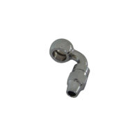
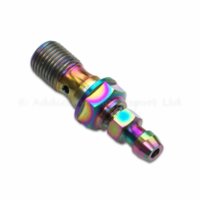
With the banjo inlet at 45 degrees, a 90-degree banjo fitting combined with a Banjo Bleeder Bolt should point me right at the clutch cable hole in the cover. 90-banjo-fitting.jpg banjo bleeder bolt.jpeg
 
Metal, it's hard to tell from your screen shot but you might want to mill the banjo port seating area flat as opposed to spotfacing, you will have to confirm that the spotface you've shown will accept the sealing washer diameter.

As per post 44 you will need to insure that the port sits far back enough that it provides fluid to the back side of the piston otherwise you won't be able to extend the piston. I think Mrriggs uses the cone from the pilot drill for the piston ( maybe 7/8 or so) and intersects that with the edge of the pilot hole for the M10 port. Just a guess...:D
 
Wow! Great info on this topic in a pretty short period of time. The 3D Printer info was really interesting. Once a proto is set up and (someone) starts production, I hereby re-confirm I am in. I also have a friend with an NC machine business if that would be helpful.

Based upon an earlier post, felt I should explain my shorthand math:
To calculate that ratio you must first calculate the surface area of the piston. You can't just compare the bore sizes.

That is correct; and the examples/numbers I generated are based upon this premise.
Using the D1=12.9mm and D2= 28mm, what we need is A1/A2 (Area 1/Area 2). Everyone knows Pi = 3.14; actually, a little more, but 2 decimal places is fine for us - this ain't the Space Shuttle - actually, guess I can't say that anymore - there ain't no Space Shuttle no more.... :shrug: But I digress...

So...
A1= PiR^2. PI =3.14, R1= 12.9/2= 6.45. Therefore PiR^2 = 3.14*6.45*6.45 = 130.6.
A2 therefore = 3.14*14*14 = 615.4
A1/A2 therefore = 130.6/615.4 = 0.21. Amazing, huh?

And you get there like this:
A1/A2 is equal to 3.14*R1^2/3.14*R2^2, if you cross out Pi (3.14) on the top and bottom, then A1/A2 = R1^2/R2^.

But as hydraulic components are (mostly) measured in diameters, its a lot easier to work in those terms. We know that Diameter = 2x Radius. So D1=2R1. But R1/R2 = 2R1/2R2, or 100R1/100R2, etc, etc. You just cancel our the constant #'s in the numerator and denominator (2, 100, etc). So as far as ratios are concerned, D1=R1. Which means that A1/A2 = R1^2/R2^2 = D1^2/D2^2.

But to make it easier to follow, calcing the ratios work best as I indicated:
(D1/D2) * (D1/D2), which gets rid of that pesky ^2 (squared) symbol.

Hope this has not been too pedantic, but the calcs can save a lot of trial and error. There are modifiers to the accuracy however, like lever free play... and the pressure plate hitting the engine cover would not be good.

As far as MC's, it would be handy to find something OE based and cheap on ebay? I'd be cautious of a smallish MC - it has to have/move enough volume to exceed the volume requirements of the slave. This also assume ZERO hydraulic hose wall expansion, which would also take up fluid.
Just my $0.02.
 
With a lathe like a mazak intergix you could do everything but the hone in one op. That includes cutting the flats, drilling and tapping the port. It is amazing what can be done when a programmer actually knows the NC.
 
Pago, Im guessing your a math teacher? :umm:

Metal, as the original poster of the thread I think you have the ability under "thread tools" to add a poll for this thread... I would add one to see what people are actually willing to pay for this... and at the same time quantify how many people are truly interested...
 
Realistically, between programming time, machine time, deburr, tools and materials for a small run you are looking at close to $150 each part, the more people that want them and the larger the run, the lower the cost will be.

This is just a guess but most shops will charge $60-100 programming per hour, $60-100 per hour machine time, $30-45 per hour deburr, plus tooling and materials. larger runs will spread the programming cost out more, material is cheaper if you get full bars, and set up time will spread out more as well. That is for just the slave, add in lines and a master and the 300 euro price from the one place is pretty close.
 
I ran this by my NC guy, and out of 7076 he though he could do it for around $150 for the slave.
While I know Mr Riggs preferred cast iron, 7076 exceeds grey cast iron in shear strength, and it has about 2X the tensile. The piston takes the point load, and stainless (like in a brake MC) would be the material of choice - I think. But the material is just a small part of the machining cost; it's all labor/time.
Obviously, the other stuff is required as well. I'm guessing/figuring $50 for a MC, and a local shop does stainless covered brake hoses for around $30.
As soon as a proto is up and running, I'd like to find a MC of the right size that looks like the brake MC.
Add it all up, and yep, you're looking at $250 to $300.
 
Well, I have the part getting 3D printed this week to check fit so stand by. I'm going to have the piston printed and then drill to fit the push rod to get the measurements needed for the final prototype.
Screen Shot 2017-03-25 at 11.22.00 AM.png
 
Here's a brief write up on my build thread with a similar design with a few 3D prints...
http://www.xs650.com/threads/bc-xs650-bobber-chopper-build.44687/page-3#post-496750

Just an FYI, 3D print quality may vary quite a bit depending on the printer, so you may have to do a bit of clean up on the bores etc... you may also want to tap the plastic (ie the M10 port) but you will need to thicken the wall material in that area (usually a configurable print setting in the print software)... edit: most printers will not do a solid "infill" as a default, therefore you will have a porous interior in the part... by selectively thickening the part in certain areas (bore walls etc) you can perform certain mechanical operations such as tapping a hole etc, this is not required for fitment checks, but helpful for assembling if desired...

a cross section view:
JNPR0IZzi8PwatC06oZ86AQF1F6Kik2TZnob=w1093-h780-no.jpg


3D print:
m6DWwTah2PIH2QJFfCGsCCNwRrmVg_v-xLXI=w1240-h698-no.jpg


:cheers:
 
Last edited:
Back
Top