Need my wiring diagram looked over

smokenjoep01

Motorcycle Freak
Messages
171
Reaction score
0
Points
16
Location
Cape Fear, North Carolina
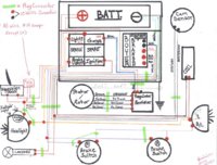
I was having serious problems getting my custom XS to charge. After talking with the Tim Parrot in Alabama. I decided to rewire the bike. I drew a diagram and would like for some others familiar, to have a look it and advise me of any potential problems.
It is a 1976 Motor in a hardtailed frame. So the big square in the diagram is the battery box. That has wires going out the side and bottom, as represented in the diagram.
I am running a Boyer Branson ignition. And the MikesXS solid state regulator/ rectifier. Also the bike uses a toggle switch and no key. As well as no Starter, turn signals, horn, high beam etc. Thanks in advance.
 

Attachments

  • XS_650 wiring diagram.jpg
    XS_650 wiring diagram.jpg
    137.8 KB · Views: 1,029
Last edited:
Welcome Joe, as there are some wiser ppl on here than I. I'm not even going to try and make sure that your schematic will work. However, I will welcome you and ask you if you have any pics of your bike?
 
Joe, look in the tech section on the wiring for the replacement rect./ reg. your using. I believe that both brushe's on the rotor have to be isolated from ground, or negative, because the ground/negative is now contolled by the rect./reg. I'm sure your answer is there.
 
That also could have been part of my intial charging problem! Hows the rest of it look? I couldnt find any info that you suggested. Could you post a link? Thanks very much for the reply.
 
I'd run a 20 or 30 amp fuse between the battery and ignition toggle. Even if your toggle will be right next to the battery. You can get a 30A rated online fuse holder or you could route that 10g wire into your fuse block and then go to the toggle.

What's the indicator light in the headlight bucket? High beam? I also don't see a dimmer switch. I'd run the power for the indicator light (if it's for high beam) from the headlight circuit instead of the main circuit.

Also, will your taillight be grounded to the frame?
Same with headlight - grounded to frame?

Like the idea of a lanyard kill switch, but not commonly seen on a street bike, more common on dirt bikes/atvs and PWC

and what's with the red wire from stator to ground?

Looks good otherwise.
 
Last edited:
I'd run a 20 or 30 amp fuse between the battery and ignition toggle. Even if your toggle will be right next to the battery. You can get a 30A rated online fuse holder or you could route that 10g wire into your fuse block and then go to the toggle.

What's the indicator light in the headlight bucket? High beam? I also don't see a dimmer switch. I'd run the power for the indicator light (if it's for high beam) from the headlight circuit instead of the main circuit.

Also, will your taillight be grounded to the frame?
Same with headlight - grounded to frame?

Like the idea of a lanyard kill switch, but not commonly seen on a street bike, more common on dirt bikes/atvs and PWC

and what's with the red wire from stator to ground?

Looks good otherwise.

Earz, Good idea about a fuse between the batt. and toggle. I will add one inline.
-The indicator light is to remind me when the toggle switch (ignition) is in the ON position.
- Yes, The headlight and tailight are grounded to the frame.
-The landyard is on there in case I decide to take this bike to the drag strip. Some tracks require it. Or if I flip it over and fall off the back spraying the motor with nitrous! Plus it gives it a cool look.:D
-The red wire I am not sure if it will be needed. The exact wiring of those componets is still a bit unclear. I need to do more research. Hopefully someone here may be able to comment that is more familiar.
Thanks for taking the time to look it over and respond.
 
-The red wire I am not sure if it will be needed. The exact wiring of those componets is still a bit unclear. I need to do more research. Hopefully someone here may be able to comment that is more familiar.
Thanks for taking the time to look it over and respond.

Do you have a red wire on your stock wiring? The factory wiring did not have a red wire going to the alternator. Unless you're using red as the ground wire (which was originally the black wire coming off the alternator)

Ungrounding the brushes will depend on what reg/rect you are using. Mikesxs sells a combo unit made for the points model and a different one for the TCI models. Which one are you using? I'm guessing that it's the points model one based on the wiring colors in your diagram. I'm pretty sure that the brushes remain grounded for that one, but check the instructions that come with it to be sure.

A 1980+ reg/rect combo (or a combo from just about any modern bike) will require you to unground the brushes. Se links for more info

http://www.xs650chopper.com/2009/09/regulatorrectifier-combo-with-points-wiring-diagram/

http://www.xs650chopper.com/2009/06/xs650-charging-system-how-to/
 
The Regulator/rectifier I am using is MikesXS part# 24-2089 for bikes 1970-1979

Solid State Rectifier Regulator - Replaces Original individual units used on
1970-79 650's. Comes with connector block/terminal kits and instructions to
wire in direct to Original wiring harness.

http://www.mikesxs.net/products-30.html#products

The stator I have on the bike with the red wire is from Mikes XS as well. The red wire goes to the screw on the brush holder.
 
If the red wire goes to the brush hold down screws then it DOES need to be hooked to ground. That reg/rect is designed for a grounded brush.

Looks like you're good to go. Throw a fuse in before the toggle and get that thing running.
 
If the red wire goes to the brush hold down screws then it DOES need to be hooked to ground. That reg/rect is designed for a grounded brush.

Looks like you're good to go. Throw a fuse in before the toggle and get that thing running.

I figured I would wire the bike, start it then get a voltage reading. Then ground the red wire and read voltage again. Just to confirm?
 
Joe, the guy to talk to is PamcoPete, that guy could straighten out a banana.
Thats funny. I posted over at the XS650 garage several times trying to resolve this issue. Pete seems short with patience and selective in answering threads. Even in forums that he is a moderator in. I did find out about Tim Parrott (very helpfull person)over there. My most recent thread over there in the electrical section, were he is moderator had 116 views and only one member responded.
It's all good! That promted me to do a little more digging, and I was fourtunate to find this wonderful forum.
 
Joe, I am not sure about the reg/rec. you are using, so that is why I sent you to him. He can be like that, though he doe's have the knowledge. I know that the wiring is posted somewhere, either here or there, 650 garage.Like you, I cannot find them for the life of me. I do remember reading that the brushe's have to be isolated on an update, but not sure if your's doe's. If that reg/rec you have is a direct replacement, then the brushe's do not have to be isolated. The brush that is isolated get's battery voltage with your key switch.I know your not using akey, but the switch need's to control the voltage to the rotor, otherwise, the battery will die because the rotor will be 'on' all the time.I am not sure what can be accessed at 650rider, but I do know that it was all there,too. What you can do is connect up tthe regulator as you had it & while the engine is running, apply battery voltage with a jumper wire to the isolated brush. Then check your voltage reading's at the battery, should be at least 13 volt's above 2000 rpm. 14 volt's is better, actually closer to spec.
 
- when replacing the separate rectifier and mechanical regulator, where the alternator brushes earth, with an earthing solid state rec/reg, you will need to isolate the brushes with nylon screws
- use nylon, not plastic screws-theyll melt www.smallparts.com...The screws are 4mm X 12mm long

stator_screw.jpg
 
I am not sure what can be accessed at 650rider, but I do know that it was all there,too.

If it was there before, it should be there now. There are still three ways to search for things on 650 Rider, using the Google search on the main page, using the search tool in the forum, and also the search tool in the gallery.
 
Thats funny. I posted over at the XS650 garage several times trying to resolve this issue. Pete seems short with patience and selective in answering threads. Even in forums that he is a moderator in. I did find out about Tim Parrott (very helpfull person)over there. My most recent thread over there in the electrical section, were he is moderator had 116 views and only one member responded.
It's all good! That promted me to do a little more digging, and I was fourtunate to find this wonderful forum.


I don't think a moderators job is to answer all the questions, he is there to keep things within the parameters of the site rules.

Are the nylon screws required on the 70 -79 stators with the 70/79 solid state R/R:shrug:
 
Last edited:
Back
Top