The danger of talking about joining coloured wires is having no idea where a particular wires comes from or where it goes to and connecting it to something without understanding the consequences.
You should never assume but test with a multimeter first in case some one else has modified the wiring or connected it incorrectly.
You should never talk about the colour of a wire without understanding the component that requires power and the function that you are looking to achieve. The colour of a wire is irrelevant ,the important thing is what it is connected to and what it achieves .
Red/white wires feed all sorts of components on an XS650 including solenoid , coils, kill switch,flasher, signal cancelling unit etc etc etc you get the picture ? you can't just grab a red/white wire and connect it to something.
What you need to do is look at the wiring schematic for your year and identify which wires supply your safety relay and how it works.
The yellow wire from your alternator should be connected to your safety relay. Its job is to power the coil of the safety relay . When you turn the engine over a small voltage is sent from the alternator to the safety relay coil which is constantly grounded . Whilst the engine is turning over the coil is energised and a switch within the relay dissconnects the live feed to your starter motor circuit preventing you inadvertently using the electric starter whilst the engine is turning over.
Depending on the age of your bike there are other safety features also effecting the power supply wire to your starter motor like the clutch lever switch and your sidestand switch . Most folk wish to disconnect these because its like the idiot bell in your car that tells you you haven't buckled your seat belt.
If you think its unlikely you are going to press the starter motor button whilst the bike is in gear with the clutch out or the engine is already running then you could dispense with the safety relay altogether.
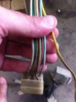
Hey guys, I've done a lot of studying and talking with XSLeo (THANK YOU). I still have some confusion though. All of these wiring diagrams I am reading over do not show the inclusion of the safety relay. Everyone says use the relay but I'm having some issues figuring out how to wire it. Looking at the starter side of the relay I have two red white wires and a yellow wire. The yellow wire I know to take it to the alt. I'm guessing, take one red/white wire to the fuse block for power, and the other red/white to the solenoid. Here is my issue. I am using a LowBro ignition switch that has a stating function by sending voltage. I realize that the solenoid requires power from one side and ground from the other, but by using the safety relay, how in the world do I inude the ignition switch? I can just get a grounding style button if I need to but we all know simplification is key. My other question is on the lighting side of the safety relay. Do I take the red/yellow wire straight to the headlight wire with an inline fuse? I'm thinking that this wire carries 12v when the bike is running. The stock setup using inline fuses vs me using an output style fuse block is confusing the crap out of me.
Thanks guys.
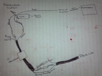
let us have a picture or link to the wiring schematic you have used to wire the bike and we can advise how you can connect your ignition/starter switch and solenoid etc with or without a safety relay

")