Vansnxtweek
XS650 Addict
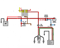
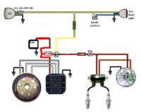
Hey Peanut, thank you for the reply and information. I apologize for the typos, sending from a cell phone is no good but it's all I can use. I also apologize for the generalization of the wire colors. As far as the red/white wire I was speaking of, I was referring to the r/w wire that is coming from the output side of the kill switch, so basically a wire that is carrying 12 volts to the ignition coil, the as well as to other components such as the safety relay I am speaking of. Solely referring to the safety relay, I have the yellow wire connected to my alternator/stator, the red/white output going straight to the starter solenoid, and the black wire to ground. The ignition switch that I am using provides a 12 volt charge, so I am thinking I can wire the 12v output of the ignition straight to the red/white input wire of the safety relay that originally recieved 12 volts from the kill switch output. I would also like to include a kill switch, but that will not be a problem. There is also a red/yellow wire coming off the safety relay that powers the headlights, so I am thinking I will run that wire to the headlights with an inline fuse. I apologize if once again that is too vague. I will try to get to a computer tomorrow and include links of the diagrams I am using.
Thanks guys.
Thanks guys.
 my spelling is so bad I have to erdit every post about 6x times to get it right.