Some wiring help needed.

Shifty2932

XS650 Enthusiast
Messages
98
Reaction score
1
Points
6
Location
Rice Lake, WI
Hello,

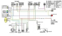
I know there are tons of wiring diagrams on this site, but I have found none really specific to what I am running. The PO who wired the bike made a mess of things and almost impossible to follow. I have recently finished reassembling the bike and over the weekend wired the bike from trying to follow the rat nest wiring job by the PO. Right now I have no spark and my battery keeps draining to nothing. Can anyone help me with a wiring diagram of what I am running?

I am running points, with a single input dual output coil and a ballist resistor. I have made my own 3 phase rectifier and also use the automotive VR-115 regulator. I am using a battery for power, keyed ignition and it's kick start only. The only things left that it am running is a single beam headlight, tail light with a brake switch. I feel that I have the wires connected right but it obviously is not working. Also which wires connect to which terminal lugs on the key ignition? I must not have labeled thingsvery well when I took it all a part and now feel like a dumbass:banghead::banghead::banghead::doh::doh:

Any help would be appreciated so I can get to riding.:bike:
 
Here is a basic wiring diagram for a single, dual output coil, using 2 sets of points. The points cam would be the stock single lobe cam. Only 1 capacitor is used.

I used a 1.3 ohm ballast resistor, with a 3.3 ohm ignition coil. It would be a good idea to add a 10 amp ignition fuse, either before or after the kill switch.
 

Attachments

  • Basic points single coil dual points.JPG
    Basic points single coil dual points.JPG
    83.4 KB · Views: 204
RG,

Thanks for the diagram. The only thing I can see missing in my current wiring is that I do not have the black wire from the regulator grounded. Would this be the cause of my issue. No spark and battery draining? Since I have an after market key switch. Could you let me know which wires go to which terminal post? I just want to make sure and double check I have things correct.

Thanks again
 
RG,

I switched over to the set up you suggested here with the coil + ballast combo last year. Good stuff, bike ran well with that set up.
 
RG,

Thanks for the diagram. The only thing I can see missing in my current wiring is that I do not have the black wire from the regulator grounded. Would this be the cause of my issue. No spark and battery draining? Since I have an after market key switch. Could you let me know which wires go to which terminal post? I just want to make sure and double check I have things correct.

Thanks again

That's a bad thing, not grounding the regulator. When the regulator has no ground reference, it supplies full voltage to the rotor field. That means the voltage to the bike and battery can go very high as you rev the engine. Voltage can reach 17 or 18 volts, which can cause damage.

No spark.....................have you checked that you have good voltage at the coil? Do you have normal resistance when you measure the coil primary?

Battery draining...............unplug the rectifier and see if the drain stops.

Key switch...................its just a simple switch. Power comes in from the battery, and goes out to the ignition and lights. Use your VOM to test the terminals on your switch.
 
Okay. So I've checked and done the tests outlined in the climber manual for no start. Points are properly grounded and gapped. No breaks in any wires. My question is, where to the points get the power from to spark when they open? Is it the ignition coil or the condenser pack? The condenser pack is the last thing I need to check. In the climber manual it states if there is no spark the condenser pack may be bad. I am going to check that today.
 
Okay. So I've checked and done the tests outlined in the climber manual for no start. Points are properly grounded and gapped. No breaks in any wires. My question is, where to the points get the power from to spark when they open? Is it the ignition coil or the condenser pack? The condenser pack is the last thing I need to check. In the climber manual it states if there is no spark the condenser pack may be bad. I am going to check that today.

I think your question is , where do the plugs get the power from to spark. It comes from the collapsing magnetic field around the coil.

Make sure your points are clean. Any oil/grease will cause high resistance and no spark.
 
RG,

Should I have any volts on the secondary side of the coil with the power on? What does the points and condenser pack have to do with ignition then?
 
Where did you buy the brand new coil, and what is it called?

Are you using old spark plug leads, and old resistor caps?

Using your VOM to measure ohms, how many ohms do you measure from one spark plug lead to the other spark plug lead? This would be the total resistance of the resistor caps, plug leads and the coil secondary.
 
http://s1020.photobucket.com/user/bmwbobz/media/Electrical/Ignition/Coils.jpg.html

I was using the red Andrews supervolt with ballast resistor (link above) Thought I had fried the coil so I bought the Harley Davidson version with oem# number provided. Original ohm of that coil was 4.2. Ohm today is 3.5. Did not install ballast resistor at first, but today I'm thinking I should as the ohm reading was lower than 4.0.

Ohm reading from cap to cap with power source and points disconnected is 20.96

Left lead reads 4.91 and right lead reads 4.69. This is from cap to end of lead.

Leads and caps are about 6 months old. Bought new last summer. Cap are NGK 5k
 
So new coil is on. Ballast resistor installed. 9v to the coil switched back to old spark plugs. Still nothing. About to stick some dynamite through the carbs and watch it go boom.

Not sure what else to do besides back tracking and tearing down the top end of the motor and starting from scratch. I had to replace the base gasket and piston rings this winter. When I put the cam shaft back in I followed the manual to make sure things were lined up properly. Cam chain is set to proper tension according the manual. Could my timing be off or is just time for new points? Could they be fried??

As far as I can tell and remember the bike is wired just as it was last year when I installed the single input dual output coil w/ ballast resistor.
 
Well I'm going to use ths method to double check that I installed my camshaft properly.
http://www.650motorcycles.com/CamTiming.html

Probably do this tomorrow. Looked at the points again. There is no film on them, but there is some pitting. Performed the check with multi meter to make sure they were closing and they are. Checked gap with feeler gauge and they are within limits. As mentioned, points are clean but they do have a bit if pitting on them.
 
The resistance readings are OK as long as 20.96 is 20.96 K ohms and 4.91 and 4.69 are with a K after them.

9 volts to the coil is about right, allowing for the voltage drop across the ballast resistor.

Lets try some basic tests to see what is what:

Test #1, disconnect the capacitor that is connected across the points. Try starting the bike with no capacitor. If no start then re-connect the capacitor.

Test #2 need to measure the points resistance. Disconnect the wire from the coil that goes to the points. Now you want to measure the resistance from that wire to (frame) ground. Select the VOM to read ohms on the lowest scale. Connect one meter probe to a good ground on the frame (bare metal). Connect the other probe to the wire that you just removed. Rotate the engine with a rachet on the alternator large nut. Every rotation of the engine one of the points will close, so that will show what the resistance is. The second rotation will close the second set of points.

Before the test, touch the leads together to see what ohms you read. If you read for example 1 ohm, then that is your new zero. If measuring the points reads 2 ohms, then that is actually 1 ohm resistance for the points.

Re-connect the wire back to the coil.

Test #3, Use a length of #16 gauge wire for a by-pass test. Put an alligator clip on one end of the #16 wire. Connect one end to the battery positive terminal. Connect the alligator clip to the junction between the ballast resistor and the coil. This by-passes the fuses, the ignition switch, kill switch and ballast. Try to start the engine or test for spark. Don't leave the temporary wire connected for any longer that needed for the test.

If it does not give spark then remove the temporary wire.
 
Back
Top