Hi,
Hoping to get some wiring help with a non-stock setup.
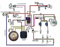
I have trouble starting my bike when warm and decided to put my starter back into service on my presently kick only setup on my 79 XS650 . I have the starter installed now and have been looking at the stock wiring diagrams and do want to use the Starter Safety Relay, SSR. The yellow wire is what I'm not sure about since I have a PMA and not the original alternator.
Is it safe to use any of the PMA output wires to the regulator? The reason I ask is that I've seen mention that to test the SSR is to not apply anything over 6V. I could reduce the voltage source for the SSR is I used the output from my regulator but then I would need a diode and tap the yellow wire between it and the regulator otherwise I would always have 12V battery voltage.
"
Safety Relay Operation
Copyright 2001 Ken Maxwell
The purpose of the safety relay is to isolate the starter circuitry once the motor is running to prevent starter gear grinding. On the early model 650's there is only the safety relay located under the right side cover just under the starter solenoid. This type controls only the starter circuitry and has nothing to do with the head light circuitry. On later model 650's (79 up) there are actually two relays. A Safety Relay (SR) that controls power to the starter, and a lighting relay (LR) that controls power to the headlight and lighting system. They can be identified by their distinct two humps.
When the ignition switch is turned on, current flows through the safety relay's normally closed relay contact to the starter solenoid. Current is stopped at the LR by it's normally open contact. When the engine is started, voltage produced by the alternator sends current through the SR, LR coils. The relays turn on and their contacts change state. The SR contact is now open and breaks the circuit to the starter solenoid. This prevents the starter from accidentally being engaged while the motor is running.
Note that the SR's operating voltage is rated ONLY about 4-6 volts. You can burn it up with 12 volts. Use 6 volts (battery charger) when testing. The LR contact is now closed and feeds voltage to the headlight and instrument lights by way of the reserve lighting module"
Appreciate help with this.
Glenn
View attachment 161412 View attachment 161414