starter solenoid or momentary switch

nb1914

XS650 Addict
Messages
167
Reaction score
0
Points
16
Location
UK gloucester
hello all,

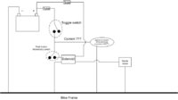
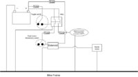
my first post but I'm sure not my last by a long way . ok so i have just purchased a custom bobber xs650 1980. the previous owner has annihilated the electrics, no key just a on/off switch on the right hand grip. starter motor disconnected. so firstly i will install a battery isolated as when the battery is connected it drains. i also want to wire backup the starter motor, i removed the starter and tested and its good. now I'm not sure what current the starter may pull i,e if a solenoid is really needed or whether a 25amp rated momentary switch would be ok ??

any comments welcome
 
The starter draws 35 amps with no load, under load it draws 100 amps.
You need a relay that can handle that much current.
Leo
 
Just about any motor cycle solenoid will do it, after all it is just a magnet operated switch.
 
Thanks guys, im no electrician. Does the below circuit diagram look ok. Im not sure what current the ignition wiring may need to cope with so where i have draw the "toggle switch" should this be something like a 40amp relay energised by the toggle switch to pass the circuit onward.

Ah
 

Attachments

  • Drawing1.jpg
    Drawing1.jpg
    26.2 KB · Views: 681
Im not sure you should have a fuse between the battery and solenoid. I think you should have a big wire attached to the battery + and solenoid and another big wire attached to the out put of solenoid and starter motor. I printed off a diagram that is found on this site under wiring diagrams, studied that and works fine. I made a couple deviations from it for my needs. There is no fuse between battery and solenoid and its hot all the time. I came off that hot lug of the solenoid and with a fuse and wired my on off switch which then goes to my fuse panel.
 
Thanks Cruzin

I think my first diagram looks ok so long as the switches are 25amp + and remove the fuse from the solenoid high current circuit. When you say big wire for the starter circuit ? i have cable with 50 strands at 0.2mm each with a max current rating of 30Amps from a previous post i guess this is not man enough ???
 
Hi nb 1914,
look at your car's main battery connections.
The bike's starter wiring should be about that fat.
Run the fat wires like this:-
Battery PLUS terminal to starter solenoid terminal.
T'other starter solenoid terminal to starter terminal.
Note that the starter's body grounds to the engine and that the engine should have a braided wire ground to the frame.
Battery MINUS terminal to frame.
The fat wires don't need a fuse.
You will run a 12ga or a 14ga wire off the battery or the solenoid's PLUS terminal with a 20Amp fuse in it to run the rest of the electrics.
Most bikes use wiring from the kill switch to activate the starter solenoid.
If you would prefer to go stone axe simple fit a mechanically operated solenoid from a model A Ford where you just push on a direct-mounted button to work the switch.
 
I like this diagram. It shows a basic points ignition with the separate regulator/rectifier.
In boxes it has various changes. Like the later combo reg/rec and the TCI. Just swap boxes to match what you have. This diagram is easy to alter for adding a Pamco, just wire it in after the kill switch.
The starter circuit is in the upper right corner.
Leo
 

Attachments

  • 314w9s3.jpg
    314w9s3.jpg
    135.4 KB · Views: 441
thanks XSLeo,

i won't be installing a key switch, and the starter solenoid has an integral pushbutton. So looking at the top right would i still need the safety relay ? basically i will install a batt isolated (red key type) from batt to one side then the other side to the solenoid (big cable) from the solenoid positive input i will link a smaller wire with 20amp fuse to the solenoid low current input and from there i will wire the rest of the electrics. So all i need to think about now is if i need that relay between the solenoid main input and link to low input ?
 
if you have a 80 and leaving stock electronics here is a simple one.
 

Attachments

  • xs650_electrical_3.jpg
    xs650_electrical_3.jpg
    77.7 KB · Views: 725
cigarette lighter or phone charger. I did not make the drawing nor did I put in a power outlet. But it is a good example of how you can wire your bike.
 
think i get it, I've decided to remove the engine to tidy the electrics and the frame. Previous owner has painted everything black which is flaking off to reveal a perfect powder coated blue frame. one question on removing the engine, in the haynes manual section 4.16 it says remove the last bolt, I'm assuming this is a long bolt all the way through to the other side , can this support the engine weight itself i.e. after removing all other fixing points, or should the engine be supported with a jack ?
 
Back
Top