Testing a PMA stator

Tom

XS650 Enthusiast
Messages
74
Reaction score
62
Points
18
Location
Australia
Hi all, I'm not getting any charge from my banshee PMA and hope you can lend some assistance.

Pics attached.

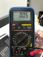
After testing my reg and my voltmeter throwing out some weird results, i tested the stator using a good VM at work. It's showing 0.05 ohm on all 3 yellow wires. Is that OK? The tests i've seen just show "1" as per - https://www.hughshandbuilt.com/2016/03/07/how-to-inspect-and-test-your-pma-system/

I expected to see some connection issues but everything appears correct and intact.

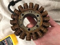
Other question is, how does the stator look? Not too dark? The metal outside surfaces had surface rust and oil built up which i've cleaned. Could this have been the cause?

Next step is to re-check the regulator...
 

Attachments

  • conns.jpg
    conns.jpg
    146.3 KB · Views: 132
  • stator.jpg
    stator.jpg
    165.6 KB · Views: 136
  • stator1.jpg
    stator1.jpg
    167.5 KB · Views: 183
  • vm.jpg
    vm.jpg
    182.8 KB · Views: 143
Your meter shows 00.5 ohm (1/2 ohm), which is ok.

Pic of your stator looks good, but check that there's no continuity to the stator frame.

For reference, here's more PMA threads:

http://www.xs650.com/threads/stator...wires-at-the-phase-connections-melting.30742/

http://www.xs650.com/threads/rotor-overheating.31505/

http://www.xs650.com/threads/almost...-advice-for-pma-stock-points-requested.40853/

Thanks for this TM, much appreciated. I just ordered a new PODTRONICS regulator that I hope I don't chew through as fast as the Chinese ones :s
 
Tom, testing the insulation resistance of the stator with a multimeter will give you misleading information. The reason is the voltage the multimeter uses to measure the resistance is to low to stress the insulation of the stator windings.
I am not suggesting you go at it with a 500V insulation resistance tester like Electricians use.
A rough enough to do the job method is to test the insulation with a test lamp and 12V battery or even better 2 in series to give you 24V.
I have an old indicator with a crocodile clip on one lead and a probe on the other, it is a very versatile and simple tool.
For testing the continuity of the stator a multimeter is the correct instrument to use as you are testing for specific resistance values to compare to specifications.
 
Tom, testing the insulation resistance of the stator with a multimeter will give you misleading information. The reason is the voltage the multimeter uses to measure the resistance is to low to stress the insulation of the stator windings.
Not exactly accurate. There's no difference between 1v and 12v as far as insulation resistance goes. It's only when you get into hundreds of volts and higher that insulation stops insulating.
 
XjWMX what you say is probably correct I don't know.

What I do know from painful experience is that testing the insulation of a CB900 stator with a multimeter will give a good reading although the insulation had failed.

Stator winding insulation has to withstand higher voltages than the measured AC voltage output of the windings.
Meters measure RMS voltage the peak voltage which insulation has to withstand is 1.414 times the RMS voltage.

I did a quick google search and found the output of a RD stator is 30-40 volts, and other bikes are higher saw one given as 75V.
If the output is measured at 35 V the peak voltage is 49.49V.
The voltage used by a multimeter to test resitance is much less.

RMS and peak values are only applicable in AC circuits.
 
Last edited:
This is sort of related so I will mention it. The stator windings of a large(ish) electric motor can hold a charge like a capacitor.
Sounds funny but when you think about it a capacitor is two conductors separated by an insulator (dielectric), and a bundle of windings are conductors separated by an insulator.
After checking the insulation resistance of a motor it is good practise to short the winding to release the stored charge. I did not do this one day and had a painful reminder to do so.
I doubt this would ever be a problem on a motorcycle alternator .
 
Tom, testing the insulation resistance of the stator with a multimeter will give you misleading information. The reason is the voltage the multimeter uses to measure the resistance is to low to stress the insulation of the stator windings.
I am not suggesting you go at it with a 500V insulation resistance tester like Electricians use.
A rough enough to do the job method is to test the insulation with a test lamp and 12V battery or even better 2 in series to give you 24V.
I have an old indicator with a crocodile clip on one lead and a probe on the other, it is a very versatile and simple tool.
For testing the continuity of the stator a multimeter is the correct instrument to use as you are testing for specific resistance values to compare to specifications.

Now i'm confused! Everywhere I've looked, it has the multi meter test or the AC test when the bike's running. How should i test this with the 12V battery? Hook the battery up to one of the three wires and the test lamp on another, then cycle through the three like that?
 
I regret the confusion I have caused you. I am off to work soon will try and clarify for you when I get home tonight.
 
Ok Tom I am back from work now so I will try to clear the muddy water.

The test you have shown in your initial test is the continuity check.

The AC check is the check done with the bike running, and you test the AC voltage across the 3 output wires, 2 at a time . To check that there is voltage output from the stator. Do this with the stator wires disconnected from the rest of the bikes wiring.

The insulation check was mentioned by 2M in post #3. It is to check that the windings of the stator are not shorted to the steel core and in turn to the bike chassis.

I believe it is best done with a voltage greater than the voltage output of a multimeter and a better way (although not as high as I think the voltage should be) to do this is with a 12V battery.
To check the stator on the bench :

Connect 1 terminal of the 12 V battery to one lead of your test light.

Connect the other terminal of the battery to the stator mount.

Check the test light by using the free lead of the test light to touch the stator mount, the test light should light (burn) , you have a circuit.

Test each stator wire in turn by touching the free lead of the test light to it, the test light should not burn if the stator winding insulation is good. If it the test light burns even dimly the stator insulation has failed.


I am not surprised you cant find a reference to this test as I had a look in a RD 350 manual I had handy and it is not mentioned in it at all. Only stator continuity.

Hope this clears the confusion up and you can get your bike charging soon.
 
Back
Top