Voltage regulator issue

Newbie

Newbie
Messages
20
Reaction score
0
Points
1
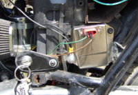
I'm working the infamous charging issue on my 78 XS.....With the key switch turned on, bike not running, I'm measuring 11.99 volts on the brown wire going to the voltage regulator, but I'm only measuring 0.11 volts on the green wire coming out of the regulator, and 0.06 volts at the positive brush.

I'm using the Chrysler regulator and the radio shack rectifiers. Shouldn't the green wire's voltage be the same as the brown wire?
 
Newbie,

The stock relay type regulator does provide battery voltage on the green wire to one of the brushes. However, the Chrysler regulator provides ground instead, and that's what you are reading. That is the reason that you have to use nylon screws and substitute battery for ground on the other brush that is normally grounded.
 
Pete,

I may have wired my regulator incorrectly. I used the NAPA regulator (part# MPEVR38SB) on 78 XS....

I cut the wires off of the old regulator and connected the green wire to the top bullet and the brown wire to the bottom bullet. I ran a separate wire from the inner brush to the brown wire with a 7.5 inline fuse. I also replaced the three metal screws with nylon screws.

The bike only charges when I bypass the regulator. My question is: do I have the regulator wired correctly?
 
I have a reg from Advanced Auto, an R92Z , RZ92. Any way it looks like this pic. The green wire to the top, the brown to the bottom. If you hooked the wires backwards and turned on the key it cooks the reg right now. Even if you swap the wires the reg is done.
Mine had a year free replacement warranty, yours might too. Take it back and get a new one. Make sure the wires are right and try again.
Leo
 

Attachments

  • LostFile_JPG_65101064.jpg
    LostFile_JPG_65101064.jpg
    189.8 KB · Views: 226
Thanks Leo, I bought a new regulator today. I'm going to give it another try tomorrow.
 
so on the stock regulator, is there a possibility the brown wire wont get used? i dont think it was wired to anything on mine when i started taking it apart. what does the brown wire do?
 
Pete,

I may have wired my regulator incorrectly. I used the NAPA regulator (part# MPEVR38SB) on 78 XS....

I cut the wires off of the old regulator and connected the green wire to the top bullet and the brown wire to the bottom bullet. I ran a separate wire from the inner brush to the brown wire with a 7.5 inline fuse. I also replaced the three metal screws with nylon screws.

The bike only charges when I bypass the regulator. My question is: do I have the regulator wired correctly?

XSleo has it right, but also remember that the case of the regulator has to be grounded to the frame. If you mounted the regulator on the battery box, that is not grounded. The battery box floats on its rubber mounts, so you have to run a separate ground wire from the frame directly to the mounting screw for the regulator.
 
so on the stock regulator, is there a possibility the brown wire wont get used? i dont think it was wired to anything on mine when i started taking it apart. what does the brown wire do?

Jawknee21,

Some of the more experienced XS650 owners may have to correct me, but I believe, the brown wire supplies battery power from the key switch to the voltage regulator, if you have a stock wiring set-up on the 79 and earlier models. I'm not sure what it does on the later models. See the wiring diagram in the thread below....

http://www.xs650.com/forum/showthread.php?t=11446

I would think that you would have to use it. My opinion for what it's worth.
 
The brown wire supplies battery voltage to the regulator so the regulator knows what the battery voltage is. It uses this voltage reading to control the power flow through the rotor by turning the power on and off to keep the alternator ouput at 14.5 volts.
If the brown wire isn't hooked up then you will get no voltage or max voltage, depending on early or late models.
Leo

So could that be why my pamco burned? So should it be connected to the red wire? I still can't tell where it goes...

Posted via Mobile
 
On the stock wiring the brown wire from the reg goes to the brown wire after the key switch.
When I rewired my 75 to simplify and fix po mistakes I wired the reg in the same as stock. Brown wire after the key switch.
I wrote a thread on how the basics of the bike electrics work. Titled Electrical Basic's or What Happens When You Turn The Key On. I explain how the 70-79 reg and rec work and how the 80 up work.
Jawknee21, yes over voltage can burn up the Pamco. It can also burn up the stock TCI. It is also harder on the points and can blow bulbs. It might even be responsible for burning up wiring harnesses.
Leo
 
I still don't get it. I gotta get someone to show me in person. I don't understand the diagrams. I can't fill in the blanks or figure out what I would change on the diagrams to make it like mine...

Posted via Mobile
 
I am having this issue on my 74 points engine. If I hook the brown wire from the voltage regulator to the brown wire on the switch, where else would it go? to the coil neg side?
Does it ever hook to a red wire?
 
I am having this issue on my 74 points engine. If I hook the brown wire from the voltage regulator to the brown wire on the switch, where else would it go? to the coil neg side?
Does it ever hook to a red wire?

Use a wiring diagram, such as this one. They are your road map to find your way.
Diagrams are in the "Tech" section.
 

Attachments

  • XS650 all years.JPG
    XS650 all years.JPG
    103.9 KB · Views: 179
If you can make heads or tails of this, it is how I wired mine but does not work..(the black going from Vreg to rec is actually green, but got it wrong in the art).yet. Ideas?? The coil is a dual fire type.
 

Attachments

  • 74 xs wiring.jpg
    74 xs wiring.jpg
    88.8 KB · Views: 178
Your diagram is not clear to me???

How many ohms is the dual ignition coil primary? If you are using points, then the coil primary should be 4 ohms or greater.

Do you have both sets of points connected in parallel? In other words, both sets connected to the common location at one side of the coil primary?

With points connected in parallel, you can only use one condenser (capacitor). Unplug one of the black leads from one end of the condenser.

The voltage regulator has 3 leads. The brown, from the reg. must connect to downstream side of the ignition switch, i.e. brown from ign switch. The green,from the reg, connects to the left outer brush on the alternator. The black, from the reg., connects to the right inner brush or connects to the common black ground wire in the harness, or connects to a good bare metal ground on the frame.
 
Ok, the coil measures 4.3ohms The condenser is a single unit with two leads. I connected both points together with both leads from the condenser to the neg side of the coil. Does the brown lead from the switch then go to the pos side of the coil? I figure since both pistons reach TDC at the same time it should work, and both spark plug leads will fire at the same time giving a "dead spark" to every exhaust stroke while the proper spark for ignition will be on the opposite cylinder.
 
Ok, the coil measures 4.3ohms The condenser is a single unit with two leads. I connected both points together with both leads from the condenser to the neg side of the coil. Does the brown lead from the switch then go to the pos side of the coil? I figure since both pistons reach TDC at the same time it should work, and both spark plug leads will fire at the same time giving a "dead spark" to every exhaust stroke while the proper spark for ignition will be on the opposite cylinder.

Yes, the condenser has 2 leads, but you need to unplug one of the leads as I previously mentioned. Only use one condenser.

There is no "positive" or "negative" terminals on the coil. It does not matter which way the current flows in the coil primary. You can connect it up any way you like.

Current flow is from the ignition switch (brown wire) to one side of the coil. The other side , of the coil, is then connected to the 2 sets of points.

Edit: When you wire from the ignition switch to the coil primary, its good practice to wire in an ignition fuse, and a kill switch.
 
Last edited:
MrYeats. What regulator are you using? If like the one in the pic in my post #4, reversing the brown and green wire then applying power will burn up the reg.
It looks to be wired right by your diagram. If the reg isn't stock I would add a ground wire from the body of the reg to ground. I'd do this by running a wire from under a mount bolt to a good frame ground or back to the battery negative.
Leo
 
So I need to remove one condenser wire. I am using a solid state regulator grounded to the frame as suggested. Brown wire to switch, fuse between switch and coil. There is a second wire on the key switch that is hot in the same position as the brown wire, is that for headlight, tail light, and horn?
 
Back
Top