First XS650 Build, What to Look For

Good point 5twins, I would not have known that and also didn't realize people don't typically pull that shaft. That said, I will be going kick only with this build so I will remove that gear and put aside, though like the electric starter itself it will not be going back in.
 
Well, if going kick only, you can remove all the starter related gearing. That would be everything in this drawing, except of course, the little gear train cover. Leaving that off would result in quite the oil leak, lol .....

StarterGears.jpg


On the right side, that would be all these gears and parts .....

4GearAssembly.jpg


..... and on the left side, all the stuff under that little gear train cover .....

StarterGears2.jpg
 
Thank you for the detailed pics on what to leave out! This is excellent and I'm excited to not have to reinsert all of those gears. Seems like such a convoluted system! Maybe I'm just not experienced enough to realize that most starters are like this, but I think I remember reading something saying that this bike wasn't designed to have this electric start and it was later added which is why it's set up so strangely.

Edit: As a side note, the gear in your last picture with the three phillips head screws...I'm not sure that was in the bike to begin with. I could be wrong (I'll check my baggies tonight) but I'm fairly certain that unit was empty when I opened it. Not that this would surprise me given the state of the bike when I bought it lol.

Edit 2: A little nervous as I approach this final step here. I've never been this far into an engine before and I'm very afraid of disassembling/reassembling incorrectly. Any words of wisdom from those of you who were once in my shoes? What was your path from novice to expert like? Give me some good stories to kill time reading the next time I hit a roadblock with the build haha.
 
Last edited:
You have those parts (1st and 3rd pics in post #109). They came out with the little gear train cover when you pulled it. The 3 screws are facing the cover so you can't see them. That stubby shaft and the gear assembly just pulls out of the cover. You'll want to re-install just the bare cover (with a new gasket of course).
 
Ahh good eye. Yes I see them now. Never saw those phillips head screws so I didn't recognize the gear. Good catch. I'll pull those off the cover tonight and label as not needed for reassembly.

Also need to get the appropriate freeze plug for the other side of that unit which would help to prevent the "minor leak" that would result without haha.
 
I messed around with a few different hardware combos but none were really the cat's PJ's
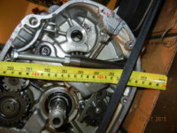
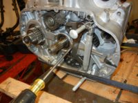
Yes about 5 1/2" overall on the turnbuckle. They are a couple of bucks each. I did split another crankcase just now. a few notes;
I was working in about a 50F garage, that didn't bother anything. After you remove all the bolts and nuts be sure you also remove all the washers. The copper crush washers can be rather firmly crushed into the stud threads holding the halves together. I grabbed an aluminum drift and went around and tapped all the stud ends a time or two so I was sure they weren't stuck in the lower case half.
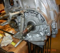
On this engine the "clutch shaft" tried to lift off with the lower, a couple of taps with wood blocks freed it from the oil seal and bearing shell's grip on the case half, it then laid on the upper half. The assembler was generous with the Yamabond on this set.
Once the seam started opening I gently used flat blade screwdrivers to help spread the gap, slowly working around the engine. Once it was open about 1/4" (or 6mm finger boy) it came off with just a bit of shifting to free it from the stud threads.

DSCN4619.JPG DSCN4621.JPG

DSCN4616.JPG DSCN4625.JPG

DSCN4626.JPG DSCN4627.JPG
 
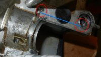
SlowMaintenance, gggGary, would you fellows mind probing around the area between the blanking plug and the mainshaft needle bearing? Curious to know if there's any hidden, interconnecting oil gallery in there, to supply oil to the trans and clutch.

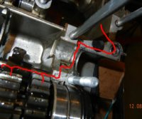
Annotated pic from YAM277's album:
HiddenGallery.jpg


It's an unresolved question in YAM277's thread: http://www.xs650.com/forum/showthread.php?t=43457
 
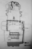
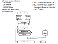
There is oil pressure to the clutch shaft. if you run the engine with the LH cover off, oil pressure pushes the push rod out and and a slow steady stream of oil comes out.

oil schematic..jpg oil pump 78 supp..png

Both cases I split are late model 79 up. I think I have a 75ish set apart also. I'll look when an early set comes apart also.
 
2M - Will definitely take a look at mine once I get it cracked open, mine is a 76 so who knows it will be any different than the ones Gary has seen. If it doesn't match Gary's photos above I'll be sure to post about it.

As for last night, managed to get the clutch side to separate using the aforementioned turnbuckle tool. However, Home Depot didn't have the type that you were using. Mine had rounded edges on both sides and was much harder to use since I had to spin the ends themselves and that gets difficult when the pressure increases. Pics below to illustrate the frustration

yp8RA2C.jpg


Very blurry but if you look closely you can see a thick black line where the case edges meet. This is a small gap and a glimpse of hope that these will eventually separate.

eJ09EOS.jpg


That said, my turnbuckle was too big to fit on the alternator side. Going to return these turnbuckles and try another pusher unit.

Gary - I liked what I saw yesterday (post #119) with the threaded stock and two clamp units. Looks like the easiest way to separate them. What is that tool?

So close here guys, tonight should do it.
 
That tool still wasn't the best, creation continues. pipe nipple and carriage bolt. about a buck at farm and fleet.

2many; I think this is what you are after.


transmission oil passage.jpg tranny oil passage.jpg

It's not obvious but a hole has been drilled from the outside through to the cavity by the second cylinder stud, then the ball bearing and gooper covers the outside opening. I positively confirmed this by spraying carb cleaner through the passage. I am sure this applies to all years. It also explains why that darned push rod oil seal leaks so often, the space between the seal and the bearing is a pressurized oil passage! Looks like the oil then is sent through the shift shaft and is sprayed out through drilled holes to the various gear pairings.

2many you are hereby charged with the duty of adding that pic to a bunch of relevant threads!
 
Take that turn buckle heat the ends with a torch, bend them to make a simple L instead of an eyelet. the leg will sit in the grooves in the sidecover and give you clearance to spin the turnbuckle. once one corner is loose slide two putty knives in the joint as far from the open section as you can get them, tap the open area back together. That will spread the other side, repeat a few times with bigger shims to spread the cases evenly. this trick works on many "splitting" jobs.
 
Interesting idea. I've got some wooden shims from my piston pusher tool lying around that could work for sliding in between the cases without fear of marring the surface. I'll try that tonight.

As for the L shape, I'm not sure that could work, because if it's an L I won't be able to rotate it without it hitting the edges of the case.
 
Using bolts in the side cover hole would step the eyebolts away from the cases so you have room to turn the turnbuckle.
You might want a flat washer and jam nut to keep the side pressure off the molded bosses.
 
...2many; I think this is what you are after.
View attachment 59587 View attachment 59588

Yes, that's it! Great pics.

... It's not obvious but a hole has been drilled from the outside through to the cavity by the second cylinder stud, then the ball bearing and gooper covers the outside opening.

You're right.
It's NOT obvious, and other pics I have don't clearly show ANY signs of a through passage emerging by that stud.

... I positively confirmed this by spraying carb cleaner through the passage. I am sure this applies to all years. It also explains why that darned push rod oil seal leaks so often, the space between the seal and the bearing is a pressurized oil passage! Looks like the oil then is sent through the shift shaft and is sprayed out through drilled holes to the various gear pairings.

Also, alongside the pushrod to the clutch.
What I've been trying to ascertain is the variations of that secret passage over the case lineage. '80-on appear to have a very visible channel. Prior to '80, we now have your '79??? with proper channel. I don't have years for the other case pics that seem to be missing the 'secret passage'. So, this should be a 'lookout' item on rebuilds.

... 2many you are hereby charged with the duty of adding that pic to a bunch of relevant threads!

EGADS! Well, okay, I've downloaded them, and have a couple threads in mind.
I'll wait for Nick's report...
 
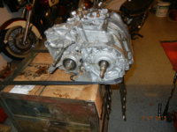
case split 001.jpg case split 002.jpg

case split 004.JPG

I had already cut my turnbuckle eyes off too short so just welded on a chunk of bolt, worked great on case split #3. Hint start the split "behind the clutch" then then go up to the alternator area, the case seems to separate easier at the back, once it's started the front is easier to open. The 3rd one let go with a pop! when it split.
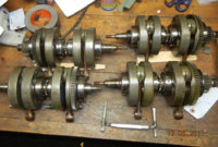
4 cranks going to Mr, Crank wizard / welder tomorrow. 2 should be good as is, the other 2 I hope will mix and match to make one good one. One of those has been hanging around forever from a dropped valve engine. but the other rod on that crank looks, feels fine....


447-203XXX or XS650C 1976

case split 006.JPG

2many you can right click an expanded image click "copy image URL" and paste it all over the forum using the pic button from the post tool menu. I do that a bunch...
 
I like your spreader tool. Wonder if it could work other places, like exhaust crossovers.

447-203XXX or XS650C 1976

View attachment 59599

2many you can right click an expanded image click "copy image URL" and paste it all over the forum using the pic button from the post tool menu. I do that a bunch...

Gotcha. That last '76 ??? pic does a great 'reveal' of the secret passage emergence.
I've downloaded the pics anyways, in case of future annotations.
 
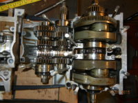
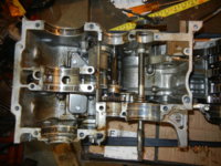
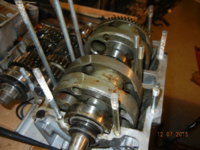
I did it! They finally came free guys. Thanks to all the awesome tips from you gurus I was able to use the turnbuckle to press open one side, and very gently using a flat head screwdriver against the gasket I was able to VERY GENTLY pry open along the edges until it was all lifted. To be honest it took VERY little pressure and came apart pretty easily with that method. I was afraid to try it at first but after hearing that others had done the same I dove in and made quick work of removing the upper case. Here's the pictures of what I've been waiting to see for weeks now.

One side
8uSNb3l.jpg


Other side
2DPXmky.jpg


I think this is the gear 5twins mentioned would be lying in their all loose leaf since I pulled the starter shaft before splitting the cases. If this isn't that gear, please let me know cause I have no idea why it would be sitting like this
NcRXbaF.jpg


Top view
QwnDmB2.jpg


This is for my own memory lol. Sharpie died so I needed a way to remember where this strange gear came from hence the colored string. I'll use this pic as a reference in case I forget what this piece was
ZHBwDIR.jpg


Close up of the gear it if helps anyone identify it's purpose
6UlWYG8.jpg


Another shot from up top
0A6G63S.jpg


Somewhere along this process, I've actually learned some valuable lessons and changed my poor maintenance habits. I decided that having achieved what I consider a huge victory in splitting the first set of cases in my history as a "home mechanic" I would pause to allow the gurus to recommend the next action before diving into and disassembling everything lol.

I've picked up all of these pieces (crankshaft and both transmission sets) out of the engine case, all can be freed easily so no issues there. They also turn freely when interlocked which is good. Outside of that though, I'm not certain exactly what comes next in this process.

Taking another look at this pic though, if you look at the crankshaft you'll see that at 12 o clock is that rod pin that people often weld in place. Mine is fairly flush w/ the crank, as I believe it's supposed to be. But maybe I should take the crank to my local shop to have it inspected? To do that, I'll need a chain splitter though, as I realize now that you can't just lift it out. If anyone has a link to a good quality splitter, I'm in the market haha.

Excited to hear about the next step and get moving on it. Thanks guys.

Edit: After fussing (and cussing) with my road star's carb last night in an effort to get to the float drain bolt on the back of it, I decided that I don't want that headache with this bobber project. Planning to run one of the joe wiseguy 2-into-1 intakes which exposes the full carb out the side of the bike. The more I work on these carburetor bikes the more I long for a setup that allows me to reach what I need to reach without having to take half the damn bike apart. Wanted to confirm that this is the proper VM36 I'll need for that setup. There was some debate in the threads I found about roundslide vs regular and I don't want any issues. Thanks! (PS: I know I'll need new jets and yes I've read the TC thread, no need to link it to me lol)
http://www.oemcycle.com/Item/product/900195260
 
Last edited:
You really don't need a chain splitter. Find the master link. It's pretty easy to spot because the factory did a rather crude job riveting the pins .....

FactoryLink.jpg


Grind those pin ends flush and tap the link out .....

GroundLink-Small.jpg
 
Wow, you're not kidding lol. So I grind them flush and it just slides out? I'll take care of that tonight then.

What about when I get a new OEM chain for the rebuild? I was under the impression I would need the splitter to put it on
 
Back
Top