"extra" oil gallery jets only to the LH side. Why?

gggGary

If not now, When?
Top Contributor
XS650.com Supporter
Messages
31,008
Reaction score
61,298
Points
813
Location
Baraboo, WI, USA
Ditto. My thoughts entirely as I flushed out a pair of crankcases today. My immediate thought was that it was to provide 'splash' for the one crankshaft bearing that isn't pressure fed but, no, that's on the other side.
 
I agree with that early post by Pamcopete. There is only so much oil available, and the pressure will decrease the further the oil goes along the oil gallery. I'm sure Yamaha engineers did flow and pressure tests when they did the initial design, as confirmed by the orifice in the line that feeds the camshaft and rockers.

There was less oil pressure available to quirt at the left side, so Yamaha put in extra holes to compensate. I think Yamaha did a good job, because I don't believe the right side runs hotter than the left.

Its just one of those mysteries that may never be truly understood.

The fact that guys have tortured these engines, with infrequent oil changes, if any oil changes at all, wrong grades of oil, and yet they are known to a very durable engine, means the oil flow design is quite good.
 
The good news is it's easy to see what passages were drilled from the outside.
Here are some variations through the years.

early production 1970 SN1500ish
70.jpg

71-73 are the same
71-73.jpg


76
76.jpg

82

83.jpg

From the looks of the early 70 case the oil jet location changed from the time they ordered the molds to when they were in production.
Note that unused boss below where they drilled the jet hole.

So it looks like somewhere between 73 and 76 Yamaha changed their mind about where to squirt oil again. What years did Yamaha race the 650? The changes suggest it WAS studied, and the 76? up design was their best shot at it or more likely; after racing stopped no further design development occurred.

Whether related or not?? But my informal survey says the RH piston is more likely to hole and or drop a valve.
 
The Yamaha factory racing manual for the XS650 -> 750cc was first published in 1972. It covers conrod mods for improved oiling, but makes no mention of the crankcase oiljets.
 
It's pretty much an all roller bearing engine, and that makes it tougher than sh*t for taking abuse, especially low oil levels.
 
They don't state it but it appears the banjo orifice is reduced in size. In combination with the fatter pump rotor this would act to increase the jet spray?
They also lowered the oil level in the crankcase, in what 1975? that cut foaming, blow by from the crank vent, and friction losses but would also reduce "splash oiling" I think 75 was also the last year for the crankcase vent "chain oiler routing" Probably not a coincidence. EPA was coming into play by then as well.
Anyone got a 74 or 75 motor they can take a pic of?
 
I have a 75 and it did not have the "chain oiler routing". After I did the brake vac valve modification I ran it to the hole over the chain. It was just plugged with a chrome plug.
 
There's no need to dig into the parts stashes and eyeball cases, gggGary. From 1974 (TX650A) through 1980 (XS650G) the only part number for the crankcase pair is 306-15100-03-00, and after that the only difference in part numbers differentiates cases with black finished uppers from those without. The case design was changed with the switch to the 447 engine in 1974 and no further changes were made after that.
 
This excerpt from the 70-73 parts manual shows the crankcase P/N 256-15100-05-00 for the early XS1-XS1B.
The variance suffix of -05 implies that there were (6) changes in those early cases.

The next generation of cases were P/N 306-15100-03-00 for 1972 (XS2) through 1980.
The 306 prefix applies to the electric-starter-equipped 1972 XS2.
The variance suffix of -03 implies that there were (4) changes in those later (referred to as 447) cases.

70-73-Crankcase.jpg
 
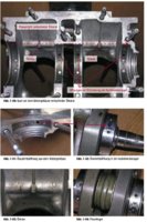
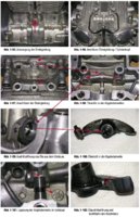
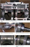
Here's a couple snapshots of the crankcase section of the German Buchauszug manual, showing the main frontal oil gallery, main bearing feed lines, and rod-end oil squirter jets.

XS650-OilGallery-De01.jpg XS650-OilGallery-De02.jpg

The english-translated versions:

XS650-OilGallery-En01.jpg XS650-OilGallery-En02.jpg
 
gggGary, I'm curious. In your LH (with the extra holes) and RH pics, is that LeftHand as viewed down into the inverted upper case, making it actually the RightHand cylinder? Or is LH the true Left cylinder?
 
Hi TM, Are you thinking of one cylinder running hotter than the other? I thought that could have been the issue until I checked the forum again. Unfortunately the extra jets are on the true left cylinder and the hot pot is on the right. Or had you thought of something else?
 
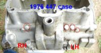
Yes 3 jets = left side
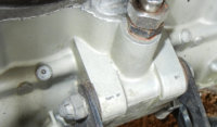
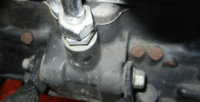
The jet holes are drilled from the outside, through the oil gallery and inner crankcase wall, a ball bearing plug is forced into the outside opening and covered with some sort of gray goop so it's easy to see from the outside what holes have been drilled.

76 case.jpg


76 case.jpg

I call sides from the riders perspective but admit I had to think out the handing here, looking upside down from the inside.
 
Thanks for the correction, TwoMany; I should have looked back farther!

Thanx, grizld1. I have a serious crik in my neck this morning from that 'looking back'. The rabbit hole is deep...

56Nomad: Welcome to the mystery. I don't know what to think about this. gggGary noticed these 'extra jets' on one of his cases, and there seems to be very little if anything published about the reasons behind the various oiling system changes. It's a fun little obsession, figuring out why things are the way they are.

gggGary: OK, great, Left is Left. This is something I'll be closely looking at on my 256 cases. The jet orifice size certainly looks small, and this would indeed warrant a better look at filtration and clean oil. Looking closely at the grainy buchauszug pic, I think I can just about make out the extra jets on the right (actually Left) side. Your pic seems to show an undrilled casting bulge on the outer right side. More mystery...
 
That heads-up on oil jet blockage is especially important given the change in Yamabond#4/Hondabond#4/Three Bond 1104 (same stuff, different labels). If the old formula was applied a bit thick it just ran down, painted the surface below the joint, hardened, and stayed put. Not so the stuff that's been sold for the last 3 years or so; it stays soft and forms blobs that can break free and travel, just like silicone sealants; and it is, of course, what's used in metal-to-metal joints like the rocker cover and crankcase halves. Put it on thin!
 
The Yamaha factory racing manual for the XS650 -> 750cc was first published in 1972. It covers conrod mods for improved oiling

Hey 3few I haven't found this info!!! And I HAVE been looking! I did a small end survey of my "inventory" and found several "hot, burned" looking RH conn rods. about 2 or 3 out of 7 or 8 sets, not counting the one hammered to a pulp.


probably the worst one. theese were all 447 rods.

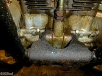
View attachment 59736
 
Yes 3 jets = left side
The jet holes are drilled from the outside, through the oil gallery and inner crankcase wall, a ball bearing plug is forced into the outside opening and covered with some sort of gray goop so it's easy to see from the outside what holes have been drilled.

View attachment 46379

View attachment 46379

I call sides from the riders perspective but admit I had to think out the handing here, looking upside down from the inside.

My 80 and 2 81's have the same 3 and 1 oil gallery set up as yours, but the RH side only has a provision for one hole and not the 2 as per your pic. The lower oil gallery is not on the case.

My 74TXA 447 engine has 2 on each side.

Check out the 75's and see what they have?
 

Attachments

  • P1030455.JPG
    P1030455.JPG
    186.3 KB · Views: 268
Back
Top