Tom you have started a second post about the same subject which is likely to lead to confusion .
")
You haven't told us..... does your alternator work ?
Are you asking us to help sort out your wiring and get your charging system to work ? or are you just curious about the source of manufacture of your pma ?
I'm assuming that your charging system is
not working and you need some help wiring up the PMA .
I have included a simple explanation at the end ,of how the stock charging ststem and a PMA system work and the various differences which should give you an overview .
.....................................................................................................................
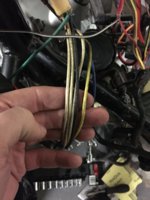
If you have confirmed that your bike has been fitted with a PMA type Rectifier/ regulator then discard the black wire from your stator.... its redundant.
Connect the 3x remaining white AC wires from the Stator to the 3x white AC wires at the PMA Rect/Regulator.
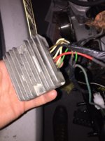
Now you'll need to connect a ground wire and a 12v+ wire to the rect/regulator but without knowing which rect/regulator you have fitted I cannot tell which wires to connect to the reg/rect other than green wires are generally ground wires and 12v+ wires are generally red, red /white or brown .
Show us a picture of your rectifier /regulator and we'll be able to tell you what to connect to where .
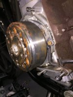
STOCK ELECTRO MAGNETIC ALTERNATOR
The standard 1979 XS650 charging system has an alternator which is electro magnetic .This means it requires a 12v+ supply and a ground (black wire ),connected to the Rotor winding in order for the Rotor to become a magnet so that it will create a 3 phase AC current in the Stator when the crankshaft spins the rotor inside the Stator.
Therefore on a standard 79 xs650 with stock charging system you would expect to see 3x white AC wires , 1x black ground wire and one green 12v+ wire coming out of the Stator to the stator plug.
There will also be a pale blue wire feeding the neutral switch and a yellow wire that controls your safety relay but we can forget those as they have no part to play in the charging system.
The three white wires from the stator connect to the 3x white wires going to the Rectifier module and can connect in any order. These carry the AC current to the rectifier which then converts it to DC voltage to charge the battery.
The black stator wire which connects to the rotor inner brush needs to be connected directly to a permanent ground (battery negative) via the frame and should normally be connected in the stator plug/socket.
The green wire takes a 12v+ current from regulator module and supplies it to the rotor outer brush via the stator plug socket. This 12v+ current going through the rotor to ground via the black wire creates the necessary electo magnet in the Rotor which can be tested by placing a metal object close to the stator with the ignition switched on, (slap test)
To avoid the battery being over charged the regulator module monitors the AC current and periodically disconnects the green wire 12v+ supply to the rotor therebye cancelling the electo magnet effect in the Rotor and stopping the stator producing an AC current .
I have tried to make this explanation as simple and concise as I can yet still maintain clarity about how the stock alternator functions. With this information is is simple to test the various parts of the charging system to identify a non functioning component, wire or connection.
If there are any errors or omissions in this text I hope someone will point them out to me so that I can make the necessary amendment.
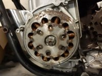
Permanent Magnet Alternator (PMA)
The Rotor of a PMA does not require a 12v+ supply nor does it require a ground so we can eliminate the green and black wires from the Stator plug . Probably best to retain the spade connectors and insulate them in case the bike is returned to stock at some future date.
The 3x white wires from the stator carry the 3 phase AC current generated by the PMA Rotor just the same as the stock charging system and that is all the wires you need to connect from the Stator to the Rectifier/Regulator.
The stock Rectifier and Regulator will not work with a PMA system and a PMA will require a dedicated Rectifier Regulator unit to regulate the batteries charging current to prevent over charging. The correct Reg/Rectifier should be supplied with the PMA alternator as a kit like the kit supplied by TCBros and others and will either regulate the DC current or the AC current to prevent overcharging.