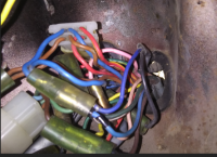
Don't think a pic could show much. I did trace each wire. One goes to left handlebar switch, one to speedo and 2 go into main harness. As my pic shows they are a dark blue. Coming back out of the main harness is a matching dark blue going to the tach harness. My meter says its the same circuit.
-
Enjoy XS650.com? Consider making a donation to help support the site.
XS650.com receives a small share of sales from some links on this page, but direct donations have a much greater impact on keeping this site going.
You are using an out of date browser. It may not display this or other websites correctly.
You should upgrade or use an alternative browser.
You should upgrade or use an alternative browser.
72XS2/73TX Wiring Diagram
- Thread starter 650Skull
- Start date
Glad you guys got this figured out.
The parking light department in the back of my head is cobweb encrusted, and old Honda schematics are cross-tangled in there...
The parking light department in the back of my head is cobweb encrusted, and old Honda schematics are cross-tangled in there...
Added a another update to post #1 XS2 wiring diagram.........Corrections????
Yes, that's looking better. Now the safety relay shows the two brown wires as it should. But the start button (actually a start lever on a '72) is still wrong. The blue/white running to it from the solenoid is correct but the other wire shouldn't run to the safety relay, it should go to ground. And it's probably black then too.
ground from start lever done......The wiring does not match the diagram......the brown wire doesn't make sense.......In a mailman pic the Red/white runs into the Coils/condensers as per diagram........red/white runs from ignition switch to kill switch.........then onto coils.....Brown wire???

The Red/Yellow wire from the ignition switch has been throwing me............Should not be there????............. Seems to me the red/yellow comes off the ignition switch 4 wire coupling, then goes to the bar switch............On the drawing it has 5 wires to/from the ignition switch.

Need some pics of original start lever wiring and some of the bucket with the wires so they can be seen a bit better.....
The Red/Yellow wire from the ignition switch has been throwing me............Should not be there????............. Seems to me the red/yellow comes off the ignition switch 4 wire coupling, then goes to the bar switch............On the drawing it has 5 wires to/from the ignition switch.
Need some pics of original start lever wiring and some of the bucket with the wires so they can be seen a bit better.....
Over the years, these bikes didn't always have a R/W running into and out of the kill switch. Sometimes it was a brown in and out to the coils, other times it was a brown in and a R/W out. What the diagram shows may not be what you find on the bike. Points coil wires are another discrepancy. Every points coil I've ever seen has a brown and orange wire. The diagrams often show the orange as a gray for the right cylinder coil. Granted, the gray points wire does connect there, but the coil wire it connects to isn't gray, it's orange.
In the starter lever/switch assembly pic you've shown, I'd say the brown is power in from the ignition switch to the kill switch. R/W is power out of the kill switch to the coils. The blue/white is the start lever wire, from the solenoid. It grounds out probably to the bars then into the headlight when you pull the start lever.
In the starter lever/switch assembly pic you've shown, I'd say the brown is power in from the ignition switch to the kill switch. R/W is power out of the kill switch to the coils. The blue/white is the start lever wire, from the solenoid. It grounds out probably to the bars then into the headlight when you pull the start lever.
Over the years, these bikes didn't always have a R/W running into and out of the kill switch. Sometimes it was a brown in and out to the coils, other times it was a brown in and a R/W out. What the diagram shows may not be what you find on the bike. Points coil wires are another discrepancy. Every points coil I've ever seen has a brown and orange wire. The diagrams often show the orange as a gray for the right cylinder coil. Granted, the gray points wire does connect there, but the coil wire it connects to isn't gray, it's orange.
In the starter lever/switch assembly pic you've shown, I'd say the brown is power in from the ignition switch to the kill switch. R/W is power out of the kill switch to the coils. The blue/white is the start lever wire, from the solenoid. It grounds out probably to the bars then into the headlight when you pull the start lever.
This is what i am trying to find out from the guys who have an XS2/TX........Using pics from known XS2's pics posted.
Mailman's Coils.......Can see the Red/White join up to the Grey and Would have to presume the orange.........Yes the coils/Condensers are Grey and Orange wires
Coils..Red/White, Hard Right....Ignition switch.....Red-Brown-Blue-Red/White
 ........


Headlight bucket.....2 different bikes....2 brown wires off the brown....2 Blue wires off the blue......single R/W or R/Y off the Red/White and single red off Red


Again need better pics and a bit more detail fro the XS2 guys
Yeah, it's a mess.
Some info on the Ignition Switch (Main Switch Assy').
256-82508-30 = 70-72 XS1, XS1B/F, XS2
256-82508-31 = Revised part number
366-82508-30 = 73 TX650
Parts suppliers claim that the 366 is NLA, and revert to the 256-82508-31 number.
Both of my XS1Bs used the 256-82508-30 switch, which uses the simple 4-pin connector. The parts manuals also show the switches for 70-73 having only 4-pin connectors.

Now, the various XS2 schematics show either 4- wire or 5-wire ignition switches, the 5-wire version with an additional red/white wire, which doesn't appear on any of the parts drawings.
On your last pic, above, the upper/right wire of the 4-pin connector is the red/yellow that feeds independant power to the left handlebar headlight switch...
Some info on the Ignition Switch (Main Switch Assy').
256-82508-30 = 70-72 XS1, XS1B/F, XS2
256-82508-31 = Revised part number
366-82508-30 = 73 TX650
Parts suppliers claim that the 366 is NLA, and revert to the 256-82508-31 number.
Both of my XS1Bs used the 256-82508-30 switch, which uses the simple 4-pin connector. The parts manuals also show the switches for 70-73 having only 4-pin connectors.
Now, the various XS2 schematics show either 4- wire or 5-wire ignition switches, the 5-wire version with an additional red/white wire, which doesn't appear on any of the parts drawings.
On your last pic, above, the upper/right wire of the 4-pin connector is the red/yellow that feeds independant power to the left handlebar headlight switch...
5Twins is correct for what I find on this XS2. Brown power to kill switch, red/white going out to coils. In a week or 3 I'm going to be breaking down my other XS2 to the frame and begin it's "resurrection". It's planned to be a multi-year process. I will have plenty of time to document any wiring questions anyone may have. What I fell is there is no one wiring diagram that will be 100% correct for every XS2. Especially when it comes to wire colors and connectors. Early production units may differ from later units. My guess is that the overall design will be consistent. Most definitely my Clymer manual is FUBAR when it comes to the ignition circuit. One thing I've noticed on quite a few threads is people get confused between production dates and model years. Other problem I learned from working on cars back in those days is that early units may have some prior year parts on them and late year units could have some parts meant for the next year.
You are correct it red/yellow.
My 2 sense, to make cents.

- Connect the blue taillight to the blue instrument bulbs.
- The ignition switch should have only 4 wires, to a 4-pin connector.
- Run the R/Y to the 4-pin connector.
- Then run the harness side of R/Y to the headlight switch.
- Connect the brown side of kill switch to harness brown.
- Connect the blue taillight to the blue instrument bulbs.
- The ignition switch should have only 4 wires, to a 4-pin connector.
- Run the R/Y to the 4-pin connector.
- Then run the harness side of R/Y to the headlight switch.
- Connect the brown side of kill switch to harness brown.
I think you got it.")
Hey guys, don't know if this is required anymore, but I pulled out my TX and it seems to agree with Skulls pics above.


Let me know if you need any other pics Skull.
Let me know if you need any other pics Skull.
2M....... i did the blue like that and then changed my mind..........Not that i thought it was completely wrong, it is the Ignition switch that was doing my head in......I agree it should be that way and the same with the red/yellow going into the Red white.........
Robin great pics thanks........... If you could separate the wires a bit so i can see where they go into double connectors and where the Red/Yellow goes into the switch loom and what other wires are on that connection.
That 6 pin connector is for the gauge cluster......
Robin great pics thanks........... If you could separate the wires a bit so i can see where they go into double connectors and where the Red/Yellow goes into the switch loom and what other wires are on that connection.
That 6 pin connector is for the gauge cluster......
Maybe this helps a bit Skull.

There is no red/white at the ignition switch. Solid red and red/yellow. I didn't catch that above. Red/white starts at the kill switch. 2 blues at ignition switch connector. One goes straight to main harness. The other goes to double connector. Second blue on left end of double goes to main harness. On right one goes to speedo the second goes to headlight switch. One of the 2 that goes to main harness one goes to the taillight. The other seems to come back out and go to the tach harness. When I tear the bike down I'll trace out the Tach wire and let you know where/how it doubles back out of the main harness to come back to the Tach.


Attachments

Bit to close and not enough of the whole bucket........When i load a pic i just drag and drop and the site resizes the pic. If the pic is large enough before dragging and drop then it is easy to blow up for details........
Like this Example only, my 80SG

Like this Example only, my 80SG
Reposting this info...........

GLJ XS650 Member
Skull
The owners manual description is wrong or maybe just confusing to me. When the key is in the park position the taillight can not be turned off. However when key is in position 1 it does go on and off with the headlight. More than once I had to stop by the side of the road. It was nice to keep the taillight on without the drain on the battery of the headlight. If needed you had the option of turning the headlight on. Can't leave them idle forever on a hot August night. I rode with quite a few Harley guys. Maintenance along the side of the road was not out of the question.
There is no red/white at the ignition switch. Solid red and red/yellow. I didn't catch that above. Red/white starts at the kill switch. 2 blues at ignition switch connector. One goes straight to main harness. The other goes to double connector. Second blue on left end of double goes to main harness. On right one goes to speedo the second goes to headlight switch. One of the 2 that goes to main harness one goes to the taillight. The other seems to come back out and go to the tach harness. When I tear the bike down I'll trace out the Tach wire and let you know where/how it doubles back out of the main harness to come back to the Tach.
View attachment 127809View attachment 127810View attachment 127811
has a continuity test been done on the blue to the taillight with the Ignition switch in position 1 and 2 in conjunction with the Lights on/off switch. This would help to identify the live circuit on the blue wires ...............this is whats missing on the diagrams