Also, a trick I've used in similar situations.... Get a radiator hose the correct ID. One that's molded with bends in it and cut out the section of bend to position the carbs where you want 'em, both vertically and laterally. Move 'em out away from the downtube.
-
Enjoy XS650.com? Consider making a donation to help support the site.
XS650.com receives a small share of sales from some links on this page, but direct donations have a much greater impact on keeping this site going.
You are using an out of date browser. It may not display this or other websites correctly.
You should upgrade or use an alternative browser.
You should upgrade or use an alternative browser.
An introduction and question
- Thread starter Jake650
- Start date
Jake650
XS650 Addict
Thanks for the likes all. But I may have opened a real can of worms for myself. (and again maybe not if a few degrees don't make any difference.  ) From reading things on this site I was aware that the manifolds changed somewhat over the years, but until I started this project I did not realize how much. I did some quick layout work on one to see what the angle difference was between flange base and carb mount, when I noticed other differences from than the one I used to pattern my manifolds. Sooooo, I need to start fresh on this and get organized so I can post what I'm finding.
) From reading things on this site I was aware that the manifolds changed somewhat over the years, but until I started this project I did not realize how much. I did some quick layout work on one to see what the angle difference was between flange base and carb mount, when I noticed other differences from than the one I used to pattern my manifolds. Sooooo, I need to start fresh on this and get organized so I can post what I'm finding.I'm once again amazed at the work that goes on among XSives! FWIW, I don't think getting the carbs exactly level is something to sweat about, there's plenty of bikes where the stock carbs aren't fitted level.
I'm once again amazed at the work that goes on among XSives! FWIW, I don't think getting the carbs exactly level is something to sweat about, there's plenty of bikes where the stock carbs aren't fitted level.
I agree - besides, when you are riding, they jiggle around so much (these bikes do vibrate a bit, I am told
") ) that I'd guess any effects of a slight tilt are not likely to be too important.
) that I'd guess any effects of a slight tilt are not likely to be too important.Jake650
XS650 Addict
After pondering this over a couple cups of coffee and input from Pete and Raymond I have to agree. I'm going to shave some of the flange off to give a bit more room for filters and drill the mounting holes. But... I still find it interesting there is an angular difference between the flange face and carb mount.
Jake650
XS650 Addict
Beags64, I did a similar check today using this. I have no idea what year it is from.

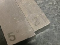
Now in full disclosure I will admit to doing my check in the most convoluted manner using way too many tools. I also thought about using my phone but then would have no way to take the pics. It's just my nature sometimes. Anyway I too used a protractor but added surface plate and angle blocks. Because of the tabs I could have simply put it on a spacer and set the protractor on it, but then I haven't used the angle blocks in awhile so why not.
I first set the protractor on the block and set my reference.

Got about 1/2 deg. off.

Stacked a 5 and 2 deg. blocks up on the plate, set the carb face on them straddling the tabs and balanced the protractor. Carefully reset the bubble to center.

and ended up right where I began at 1/2 deg.

I fall into the very small shade tree category of mechanic and can see only float function being affected by angle. How much it changes performance is way beyond me.
Now in full disclosure I will admit to doing my check in the most convoluted manner using way too many tools. I also thought about using my phone but then would have no way to take the pics. It's just my nature sometimes. Anyway I too used a protractor but added surface plate and angle blocks. Because of the tabs I could have simply put it on a spacer and set the protractor on it, but then I haven't used the angle blocks in awhile so why not.
I first set the protractor on the block and set my reference.
Got about 1/2 deg. off.
Stacked a 5 and 2 deg. blocks up on the plate, set the carb face on them straddling the tabs and balanced the protractor. Carefully reset the bubble to center.
and ended up right where I began at 1/2 deg.
I fall into the very small shade tree category of mechanic and can see only float function being affected by angle. How much it changes performance is way beyond me.
Attachments
Not sure either if the angle would have any adverse affects of performance. I guess if float level could be tweaked one way or the other and still not cause a sever lean/rich condition or an overflow problem it's worth a shot.
The angle is hopefully gonna work in my favor as I attempt to make what I believe to be BST34 from a GSXR work. Inverting the holders to effectively double the angle seems to bring these back to level.

The angle is hopefully gonna work in my favor as I attempt to make what I believe to be BST34 from a GSXR work. Inverting the holders to effectively double the angle seems to bring these back to level.
Because the floats' center of buoyancy and the jetting pickups are located at the center of the float bowls, variations of up to +/- 45° of carb angle are tolerable. If that weren't the case, then you'd experience severe fueling problems during acceleration and braking. In fact, it helps to angle the carbs forward on dragbikes...
I think you'll be fine,
As long as you avoid inverted riding...
As long as you avoid inverted riding...
Jake650
XS650 Addict
2M, Your input is greatly appreciated.
Jake650
XS650 Addict
Thought I would give an update as to what is going on in the shop. While waiting on parts for the XS1B project I started getting things ready to put an electric start back on the orange bike. Starter I had needed disassembly and cleaning which resulted in the screws holding the end caps on being drilled out. No big deal but now I need to order some 10-24 HeliCoils so I can replace the original screws. But while having the oil drained out I decided to put a modified sump filter in. So to all you Air Frame./ Air Power mechanics out there I'll fess up to my first safety wire job and comments as always are welcomed.

So while again waiting on "stuff" to complete adding electric to the orange bike I thought I would get some XS1B stuff done. My fork tubes were in rough shape so I bit the bullet and ordered new tubes from Franks Forking. When I ordered them I asked the guy about the end caps and he said I would need to remove my originals and put them on the new ones. No big deal I thought until I gave it a go tonight. From what I see the end caps are held in place with pins in a blind hole.
This pic shows the pin at about 11:00 and looking inside there is a hole. They do not share a common dimension. The pin is about .600" from the cap end and the hole is about .900". Now I know you cannot see the inside of the tube to see if the top hole goes through but there another pin 180 degrees from the one shown and as you can see there is no through hole for it. I welcome input on how others have done this but for now I see my options as setting up the part in the mill and drilling out the pins or making new caps that are a press fit on the tube with the addition of a press fit dowel to ensure things stay put.
Did the same thing on my starter. I found that 10/32 screws were a perfect fit with no modification to the threads on the end cap. Have a look here.Starter I had needed disassembly and cleaning which resulted in the screws holding the end caps on being drilled out. No big deal but now I need to order some 10-24 HeliCoils so I can replace the original screws.
Jake650
XS650 Addict
Jim... .  Well the wait for HeliCoils is over, as tomorrow I'll make up a couple of 10-32 studs and finish the job.
Well the wait for HeliCoils is over, as tomorrow I'll make up a couple of 10-32 studs and finish the job.Just a heads up I never mentioned in my resto thread. I wound up cutting the studs flush with the nuts to clear the frame when I installed it. It's that tight.Jim... .

Jake650
XS650 Addict
Well, got the starter together with a couple of home made screws.

Should be low enough profile but it not back into the lathe they go. I also got the oil drained and all covers off to fit the starter but waiting on a couple of new seals from Mikes before I button it up. I started looking into what was needed electrically and dug up three starter solenoids. Of three one should be good. So with what parts I have it was time to break into the manual and begin figuring out the wiring. Which leads me to the starter cut out system. The Yamaha manual says the tachometer control shuts down the starter circuit when the engine is running. This brings me to my questions.
1. I'm running an after market mini tach with no electric inputs. This means I have no inputs to cut off the starter so what is a person to do?
2. Is it possible to run the shut off signal from another source?
3. Is the starter cut off circuit absolutely necessary?
Starter cutout comes from the alternator. There's a single yellow wire that goes to the cutout relay.

Jake650
XS650 Addict
Jim, thanks and I've been trying to digest the diagram. It may be dinner but most likely me not getting it that is not setting right. I do not have a lighting relay. My lights are wired with a single pole double through switch. So i'm guessing the lighting relay in your schematic can be dropped of in my case. If the starter relay is separate what does it look like? I have a few parts but no idea if any one of them is the relay.
I do not have a lighting relay. My lights are wired with a single pole double through switch. So i'm guessing the lighting relay in your schematic can be dropped of in my case. If the starter relay is separate what does it look like? I have a few parts but no idea if any one of them is the relay.Attachments
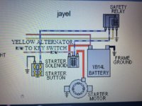
It's a plate mounted to the right side of the battery box. Might be on the left on some yearsIf the starter relay is separate what does it look like? I have a few parts but no idea if any one of them is the relay.
Contains both the light and starter relay. There's also some years with just the starter relay. Don't have a pic for them. If you don't have it you could just use an off the shelf relay. Let me know if you go that route and I'll give you a link to the ones I buy.