Anyone seen a simplified Boyer wiring diagram?

alfredo

1978 xs650 Special
Messages
1,034
Reaction score
16
Points
38
Location
Los Angeles, CA
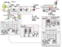
I found this one, but it has turn signals and all kinds of stuff.

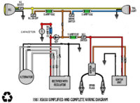
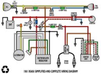
I am wiring a kick only, 12v battery, headlight (hi/lo), taillight, boyer brandsen kit and standard charging system.

Would almost pay for someone to draw up a nice clean easy to follow diagram. . . looking at the full diagrams blows my mind.
 
Last edited:
Also, when I disassembled my bike. . . . it had no regulator or rectifier and it was running . . . ?

I am confused by this as I went through my parts bin and the photos I took of the bike when it was together and don't see a regulator or rectifier anywhere. . . am I not supposed to have one with the boyer brandsen?
 
You have a DYNOMO BOX which is a REG/REC not ignition
Go to BOYER site they have them all listed
 

Attachments

  • pb.jpg
    pb.jpg
    17.2 KB · Views: 195
Ok. I think I am confusing some people (or myself).

So, I am pretty sure that I never removed a Regulator or Rectifier from the bike, but in that diagram it lists one. The bike was running when I took it apart and I took 100's of photos of the tear down. No Reg or Rect in sight.

So, when I look at the wiring diagrams I am not sure how to wire my bike up because they all list that Reg/Rect. . . . . . ?
 
So this has nothing to do with the Boyer? You just can't find your reg/rect. Do you still have the stator and the original harness? What year bike? Pre 80 was 2 seperate units, one weird looking with a 8mm stud, and the other is a rectangular thing , looks like a big relay. 80 -up will be one aluminum finned unit with a 6 wire plug.
 
So this has nothing to do with the Boyer? You just can't find your reg/rect. Do you still have the stator and the original harness? What year bike? Pre 80 was 2 seperate units, one weird looking with a 8mm stud, and the other is a rectangular thing , looks like a big relay. 80 -up will be one aluminum finned unit with a 6 wire plug.

I have the original stator and harness that is connected to it. I don't have the whole harness anymore. The bike is a 1978.

The only thing I see in the pictures is this long black box. Could this be something . . .:
boyer.png


If I can't find either of these, would it be ok to go buy the Dodge Dart regulator? I am going to wire this simply.
 
Ok, your 78 will have 2 seperate units. I honestly don't remember where they were originally. But you really don't want to use them anyway, they are 30+ years old nad sucked when they were new. Yeah, you can do the Radio Shask rectifier and Chrysler regulator, you'll just need to isolate the brush wires. There's several threads on here. It's easy.
 
Ok, your 78 will have 2 seperate units. I honestly don't remember where they were originally. But you really don't want to use them anyway, they are 30+ years old nad sucked when they were new. Yeah, you can do the Radio Shask rectifier and Chrysler regulator, you'll just need to isolate the brush wires. There's several threads on here. It's easy.

Thanks. This solves my issue.
 
Here's a few piocs that might help on the Chrysler reg and Radio Shack rec. They go along with the pm sent.
 

Attachments

  • 314w9s3.jpg
    314w9s3.jpg
    135.4 KB · Views: 465
  • combo3.jpg
    combo3.jpg
    25.3 KB · Views: 284
  • im001392nb6.jpg
    im001392nb6.jpg
    44.6 KB · Views: 254
  • LostFile_JPG_65101064.jpg
    LostFile_JPG_65101064.jpg
    189.8 KB · Views: 202
The first pic is a diagram I got from Jayel. It shows several options, depending on the parts you have.
#2 shows how the regulator and rectifiers are wired.
#3 shows a pic of the actual Radio Shack parts on the plate and wired up rectifier.
#4 is how the Chrysler regulator on mine looks mounted where the stocker was, on the side of the battery box. You can't see the rectifier, it's mounted in the stock place under the battery box.
 
Thanks XSLeo!

I have a few questions . . .

I am reading (and doing) this thread and it says:
3. Remove the ground connection from the inner brush.
Which is the "inner brush" and what exactly is the "ground"?

Step 5:
5. Run a wire with a 7.5A inline fuse from the now isolated brush to a source of +12 volts from the ign switch (brown wire)

And it says in the image "From Fuse or Brown Wire". I have a brown wire in the harness of coming from the brushes or stator, but should I ignore this wire and run a new one with a 7.5 amp fuse? Also in this step it says "to a source of +12 volts from the ign switch", does this mean connect it to a wire from the ignition and also to the other connector on the regulator?

I have a blue wire in my harness as well, what should I do with this wire?


thanks everyone!
 
Alfredo, on your stator there is a nut that holds the rotor on. This nut is in center of the alternator. On your brushes the one closest to the center is the inner brush. The one farthest from the center is the outer.
The inner brush is held by three metal screws. there is a black wire hooked under one screw. This wire hooks into the black harness ground wire. The three metal screws ground the brush to the body of the stator.
I have a pic of the 70-79 stator. It shows which screws you need to change to nylon screws.
If on your brushes there is a brown wire hooked to the inner brush and a green wire hooked to the outer brush then you have an 80 and up stator. An 80 and up stator has the inner brush ungrounded. No need for the three nylon screws.
I don't have a pic of an 80 up stator. I'll see if I can find one.
 

Attachments

  • nylonscrews2.jpg
    nylonscrews2.jpg
    46.7 KB · Views: 191
I found one, it shows where the full avance lines up. In the upper left corner you can see the brushes. A brown wire hooks to the inner brush. If yours looks like this, it's a 80 up stator.
As far as wiring up the Boyer, follow the directions on the Blue box. In the diagram I posted if you find the kill switch, any ignition you choose just hooks in after the kill switch.
 

Attachments

  • advance1.jpg
    advance1.jpg
    49.9 KB · Views: 274
Back
Top