charging question… Need help

loradoxs

XS650 Member
Messages
17
Reaction score
0
Points
1
Hey all,

Well I finally wired up by xs650 bob/chop and took it on it's inaugural run. It started right up and since it was late I just took it on a quick run around the neighborhood just to make sure it was running well.

I went to go take it for a ride today (5 days after taking it for its first ride) and the battery was dead. I charged it up for just a few minutes. It started right up. It's a kickstart only. 3 miles down the road... battery dead.

Obviously the bike isn't charging when it's running.
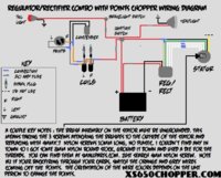
Here's my wiring:
1) wire from positive battery terminal to "Power" on the key switch
2) Pamco Electronic ignition to "Ignition" on the key switch
3) Headlight and taillight running to "ACC" on the key switch
4) Reg/Rec black wiring running to neg battery terminal and red running to positive battery terminal.
5) I have the brown wire from the Reg/Rec and the black from the stator rotor combined and a wire from that leading to the "ACC" on the key switch.

So:
A) First do I have the wires all set up correctly?
B) How do I check to see if the Stator is charging the bike?

I have a multimeter, but not sure where/how to check for problems.

Any and all help is greatly appreciated.

This bike has been a thorn in my side from day one.
 
Click on "Tech" at top of this site. Go down to "Electrical"..............wiring diagrams. Many examples there for you.

Select the muti-meter to Voltage.........20 volt scale. Read the voltage across the battery terminals.
engine off............12.5 is normal
engine idling..........13.5 is normal
at 3000 rpm...........14.5 is normal.

report back what you read
 
Well…

I haven't had time to charge the battery to get it started. But this is the information I have:
1) Engine off…. 12.07 on the battery terminals
2) Brushes are .590 in length
3) Rotor measures 5.0 ohms

I have looked up and down through all the different wiring diagrams. I haven't found one that shows where the wire connection should be on the key switch for the wire that runs from the brown reg/rec and the black from the stator/rotor assembly. Please let me know if this may be my problem.

Thanks for any and all help/advice/knowledge/etc.

I currently have it connected on the "ACC" part of the key switch. Is this right?
 
The key is going to be what is happening to your bike when it is running...what is the battery voltage at idle; etc.
The five day drain sounds like a bad ground???
 
When you say bad ground. do you mean from the negative battery post to a ground on the frame?

I have a 14 gauge wire running from the negative battery post to the battery box.
 
On stock bikes the battery box is rubber mounted, so battery negative must not be connected to battery box....................if your chop/bobber has the battery box mounted directly to the frame, then that would be OK. 14 gauge not heavy enough................maybe 8 gauge stranded.

Voltages with engine running??
 
The battery box is mounted directly to the frame.

I don't have the voltage with the engine running. I'm hoping to get that this weekend.

I found an old simplified wiring diagram and it looks like the wire from the reg/stator should run to the "battery/power" terminal on the key switch. I have it hooked up to the ACC terminal on the key switch. I wonder if that is my problem?
 

Attachments

  • wirepan[1].jpg
    wirepan[1].jpg
    105.7 KB · Views: 101
Last edited:
Normally there are 3 wires coming out of the key switch. Blue, red, brown. Blue goes to the tail/running lights. Red to the reg/rec thru fuse to battery. Brown is a main vein and picks up the brush, reg/rec, brakes, flasher, horn (if you have them). The red white comes off the coil, picks up the ignition, then to kill switch. Now this is for a TCI stock or simplified wiring. I'm not sure about the Pamco, but I know there are several diagrams in he "tech" section under "electrical" or search Pamco wiring.
 
That diagram looks to have come from a 70's era Easy rider magazine. The way you have the switch wired is fine. How you have the rest wired is the question.
Is your reg/rec a late model 80 up? If so you have the brown wire, the red wire and the black wire right, what about the green wire? The three white wires?
On the wires coming up from the stator, You have the black wire joined to the reg brown wire. Did you unground the black wire brush with the three nylon screws?
The more info we get the better we can help you. Can you post a wiring diagram of what is on your bike.
Putting your bike info in your signature will help to. Year, model, mods.
From what little you have told us you have a 79 or older bike, converted from points to a Pamco. Stock alternator with a later model combo reg/rec or one from Mike's or someplace. We need to know these things for sure.
 
Yes it is a late model reg/rec brand new from Mikes. Yes I ungrounded by using the three nylon screws.

You have all the details correct. It is a '79 and I'm running just a headlight, taillight, brake light. No electric start, just kick start. Sorry I don't have my bike description in my signature. I'll have to do that.

I've attached a diagram much like the one I'm using. It shows points. I have electronic ignition. As you can see from the diagram the brown from the reg/rec combines with the black from the stator/rotor assembly. That in turn goes to the key switch.

I'm just wondering if that wire should be hooked up to the ACC terminal on the key switch, the Battery terminal on the key switch, or the ignition terminal on the key switch.

Thanks,
 

Attachments

  • noid-chopperwiringdiagram.jpg
    noid-chopperwiringdiagram.jpg
    278.2 KB · Views: 102
The way you have it wired looks ok.
On your switch, when in the "on" position the ignition terminal should be at battery voltage. Is the acc terminal? If so hook the ignition to the ign terminal and every thing else to the acc terminal.
If only the ign terminal is hot hook everthing to the ign terminal. The main thing is when the switch is on power goes out to everything. And to nothing when turned "off".
Do you have battery voltage at the black wire brush? How long are the brushes? Have you checked the ohms of the rotor and stator?
5 ohms on the rotor, slip ring to slip ring, infinity to ground.
On the stator .9 ohms between the three pairs of white wires, infinity to ground.
Do the rotor ohms with brushes removed. Do the stator ohms with it unplugged from the harness.
If the rotor and stator check ok and you have battery voltage at the brown wire at the reg/rec and the black wire brush and you still have no charge the reg/rec may be faulty.
While running, meter hooked to battery, jump the green reg/rec wire to ground. this bypasses the regulator part of the reg/rec and puts full battery voltage thru the rotor. This should make the battery voltage climb. if it climbs don't let it go higher than 15 volts. If the green wire jump gets the voltage to climb the regulator is not working.
If it doesn't climb then something else is wrong. Check all the wiring, connections, and fuses.
 
Hey XSLeo... Thanks for that reply.

Yeah there isn't any power going to anything when the key is off.

I charged the battery and put it in. At the terminal it read 12.75 volts. As soon as I started it, the number started to drop... slowly.

I checked the rotor. it is at 5.9 ohms, but when I just touch the two wires from the multimeter together it comes up as .8 ohms, so I think everything is good there?

The brushes lengths are good, but I did find that one of the wires on one of the brushes is super thin. I've attached a photo of it. I'm wondering if this could be the culprite?

The connections look good and the non of the fuses have blown. The reg/rec is a new one from Mikes... so I've got to think that it's good.

I haven't done the other tests yet. I ran out of time. Let me know what you think of the brush.
 

Attachments

  • GEDC2463.jpg
    GEDC2463.jpg
    260 KB · Views: 117
I agree with RG on the brush. As frayed as the wire is I doubt it is delivering full current to the rotor. It is bad, but it may not be all the trouble.
If the charging system isn't working the battery voltage will drop. The ignition depending on the coil draws at least 3.5 amps, probably 5 or 6. This will discharge the battery in about 2.5 to 4 hours.
On your rotor test checking the lead to lead ohms is good. You subtract that reading from the reading you get when testing the rotor or anything you test with low ohms to get the actual ohms. So your 5.9 - .8 = 5.1 well with in the 10% tolerance. Your rotor tests ok.
On the stator checking the lead to lead resistance just before you test the white wires is needed there. If the leads still check at .8 ohms you should get about a 1.7 ohm reading on the white wires. The reading should be .9. .9 +.8 = 1.7
The stator is much less apt to go bad than the rotor. The rotor runs hotter, heat is what does most of the damage.
While you are waiting on the brushes you can check the stator ohms.
When you turn the key on do you get battery voltage at the black wire brush? If you have a kill switch leave it off to run the voltage checks. If no kill switch you might want to unhook the coil to lower the risk of burning out the coil while doing the voltage checks.
 
Back
Top