Charging system not working

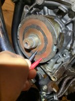
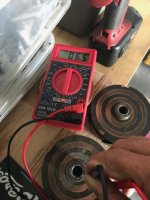
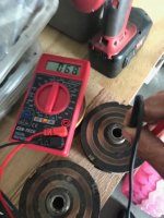
Caleb if you are only reading under 1 ohm between the rotor rings then your rotor is kaput I'm afraid. You'll need to source another rotor or best of all have Jim,( one of our members) rewind your rotor.

You might find something in this video helpful
 
Okay so I just tested it again following your instructions. Testing the leads together gives me 1.7 on my voltmeter. When i put them on the rotor it reads the same, 1.7. I will upload pictures just because I’m not 100% sure that i have my voltmeter settings right and so you can see exactly where i place the leads. First picture is my voltmeter setting. Second picture is where i put the leads. Thanks everybody!
 

Attachments

  • 09A92312-EAF1-4499-B14B-9254DA79E9CC.jpeg
    09A92312-EAF1-4499-B14B-9254DA79E9CC.jpeg
    165.2 KB · Views: 107
Not sure if that second picture uploaded. Here it is again just in case
 

Attachments

  • B773B151-BEBF-47A2-A390-471EA5AC0EA7.jpeg
    B773B151-BEBF-47A2-A390-471EA5AC0EA7.jpeg
    133.3 KB · Views: 116
The copper lands of your rotor are filthy!.....you will never achieve an electrical connection with those. use some 120 grade wet and dry as I show in my video to clean the copper up so it shines .

That could be your problem right there .....the poor electrical connection your brushes have with the rotor coil.


this is your 200 ohm setting you should be using ..........you have yours set to 200 megohm see if you can download a user guide for your multimeter

multi.jpeg
 
Last edited:
Yup - I was going to make exactly the same two points:
  • Use the 200 ohm setting not the 200 Meg-ohm (that is 1 million times too high!)
  • Everything you measure with an ohm-meter must be clean, shiny and dry.
I know these points might seem picky Caleb - but stick at it and we’ll help you get there.

Multimeters may seem complex, but once you get the hang of it, they’re not too bad really.

Cheers,

Pete
 
Chrome cleaner on a rag does a nice job cleaning up the rings. No worries about removing material from sanding. Here's the outer ring on mine cleaned up with the chrome cleaner, the inner ring not done yet .....

GHoeRsM.jpg


id1CxSs.jpg


Sometimes you really have to push the meter probes into the rings hard to get a good reading. This often times leaves a divot or dent. For that reason, take your readings along the outer or inner edge of the rings where the brushes don't ride.
 
By all means clean the rotor and try again....but something doesn’t seem right if you were reading 1.7 with the test leads shorted together( on a 200 mega-ohm scale) and 1.7 measured on the rotor on the same scale. Can you try another meter or some other test leads?

I had a look at the first two pictures you sent. It seems as though you had the meter set to the correct setting of 200 ohms for those measurements and you got two measurements one of 3.3 ohms and other was a bit higher. The 3.3 ohm measurement is a good number. Clean the rotor and try again. Could be the dirty rotor was giving you inconsistent measurements.
 
Last edited:
Don't worry about taking off a few microns of copper ...some DIYers like to worry about nothing and try to make a big mountain out of every mole hill :laugh: there is plenty of material there and it would take hours of sanding with 600 grade to make any appreciable difference ;)
Just take your time and be careful not to do any damage to rotor whatever you use . Pete Pamco suggests using a pencil eraser but the oxidation and dirt on your slip rings look too bad for that to be effective.

Hans J Pahl suggests the use of a fine grade abrasive paper of 600 grade or fine wire wool.
I always use a piece of wet and dry that is well worn not fresh which cam often be too abrasive. There are no hard and fast rules just use your commonsense and use whatever is effective;)
 
Last edited:
Update! I bought myself a new multimeter and cleaned up my rotor tonight. I am pretty sure I have everything in order now. And i think i need a new rotor. Putting the leads together reads about .02-.05 (it tended to fluctuate) when i put the leads to the rotor it read . 05. I will upload pictures as evidence!!

Thanks everyone!

Second photo is me putting the leads together. Third photo is the results of the leads on the rotor.
 

Attachments

  • 1D9C22CA-7A9D-44A8-96B7-2EC47BC464C6.jpeg
    1D9C22CA-7A9D-44A8-96B7-2EC47BC464C6.jpeg
    178.9 KB · Views: 139
  • 708F85A2-73A1-469D-85B9-7B987BB5FC25.jpeg
    708F85A2-73A1-469D-85B9-7B987BB5FC25.jpeg
    178.3 KB · Views: 138
  • 6728F93E-5149-49BA-8EFF-93579CD914F3.jpeg
    6728F93E-5149-49BA-8EFF-93579CD914F3.jpeg
    152.4 KB · Views: 118
I got two spares if you want to buy one $35.00 shipped to your door
PICK ONE if interested
 

Attachments

  • rt1.jpg
    rt1.jpg
    62.7 KB · Views: 123
  • rt2.jpg
    rt2.jpg
    58.6 KB · Views: 105
Got one of them too
SOLD!!!! Today sorry
 

Attachments

  • C24FCADC-6BF8-403F-810E-2BD32BA163DF.jpeg
    C24FCADC-6BF8-403F-810E-2BD32BA163DF.jpeg
    204.5 KB · Views: 126
Last edited:
Back
Top