My first thought was 'chuck it up in the lathe and trim back the flange'. Then realized that the cam end probably needs depth clearance in there. Time for some measuring. May need to space them out, or worse, a combination of cutting-off the cam ends and flange trim-back...
-
Enjoy XS650.com? Consider making a donation to help support the site.
XS650.com receives a small share of sales from some links on this page, but direct donations have a much greater impact on keeping this site going.
You are using an out of date browser. It may not display this or other websites correctly.
You should upgrade or use an alternative browser.
You should upgrade or use an alternative browser.
Flattrack racer build
- Thread starter Champion750
- Start date
-
- Tags
- tracker
racerdave
^ Gone not forgotten ^
These have been brought up before. ypu need a special ignition that doesn't run of the cam end, and maybe there is some cam mods.i don't remember. Search for shell.
Found it:
http://www.xs650.com/forum/showthread.php?t=32450&highlight=shell+cam+covers
Found it:
http://www.xs650.com/forum/showthread.php?t=32450&highlight=shell+cam+covers
I sold over a hundred shell cam covers , never had a problem. Just make sure you have the cam bearings all the way in and centered. Of course depending on who made them of course you may have to take a little off the edge.I looked at your pictures , your cam bearings do not look in all the way, show me a picture head on in front. You should not be able to move cam side to side back without moving bearings also. Looking at the covers the look ok. As far as ignition we use to run ARD until Allen stopped making then . we went to PVL's .
Last edited:
650performance
XS650 Addict
They do look trick, but I've always used the stock bits and never had a leak. You could cut the depth of the lip or try to source a narrower bearing, but that seems like overkill.
Will work fine with Powerdynamo PMA/CDI system. Crank triggered, great quality
I agree with arcicxs on the powerdynamo system. and the cam cover will work. I used the ignition one season racing and worked good. The system is very well built, good support from them also. I went back to the PVL on the next motor mostly for cost.. They do have a nice feature with the advance cure box. But never took the time to play with it much. I usually the ignition in stock.
Back to the Shell covers if you decide not to use them let me know I will take them off your hands, working on another 750.
Back to the Shell covers if you decide not to use them let me know I will take them off your hands, working on another 750.
Champion750
XS650 Addict
Well after some work I finally figured out how to get the cam bearings on by hand after the cam chain was in place.
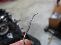
First I had to take some material off the one bearing race on the cam that wouldn't allow me to slip the bearings on the cam by hand. I use a combination of a mill fine file and 320 grit sand paper to remove about .ooo5". My method might raise some eyebrows but I sure wasn't going to send the cam out to a machine shop to have a half a thou removed. That would have taken way too long. Anyway, it worked.
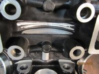
Then, the cam bearings wouldn't fit into their bores in the head so I had to make these spacers so I could torque down the head to increase clearance. Even after torquing the bearings only barely fit. I sure hope getting them off isn't an act of congress. The head and rocker box will probably go on and off two more times.
I also removed a little material from the rocker box cam chain tunnel to make room for the cam sprocket bolts.
Next I need to disassemble everything and measure the clay I put on top of one of the pistons. This will help determine which head gasket to purchase. The one I used here for measuring is the Mike's composite gasket which I believe is in the .060" thickness range. The valve to piston clearance with this gasket isn't even an issue.
Somewhere during all this I need to degree in the cam too.
First I had to take some material off the one bearing race on the cam that wouldn't allow me to slip the bearings on the cam by hand. I use a combination of a mill fine file and 320 grit sand paper to remove about .ooo5". My method might raise some eyebrows but I sure wasn't going to send the cam out to a machine shop to have a half a thou removed. That would have taken way too long. Anyway, it worked.
Then, the cam bearings wouldn't fit into their bores in the head so I had to make these spacers so I could torque down the head to increase clearance. Even after torquing the bearings only barely fit. I sure hope getting them off isn't an act of congress. The head and rocker box will probably go on and off two more times.
I also removed a little material from the rocker box cam chain tunnel to make room for the cam sprocket bolts.
Next I need to disassemble everything and measure the clay I put on top of one of the pistons. This will help determine which head gasket to purchase. The one I used here for measuring is the Mike's composite gasket which I believe is in the .060" thickness range. The valve to piston clearance with this gasket isn't even an issue.
Somewhere during all this I need to degree in the cam too.
Attachments


What? not sure what you are doing wrong but maybe you should stop. Send it to me before any more damage is done. I have been putting these together for years and never and I repeat never had to modify the cam to get it to
I re-read this and did not like what I wrote.. a little on the know it all side which I apologize for, Gary
I re-read this and did not like what I wrote.. a little on the know it all side which I apologize for, Gary
Last edited:
Check that the cam bearings you are using have the correct suffix that indicates the fit on the shaft.
The correct SKF bearing number is 16005/C3. The C3 indicates a sliding fit.
The correct SKF bearing number is 16005/C3. The C3 indicates a sliding fit.
Champion750
XS650 Addict
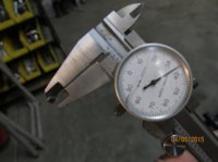
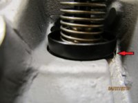
First of all, when I measured the bearing races on the cam (red arrow), one side was .001" larger in diameter than the other. I measured in numerous places and my outside mic is clean. And thanks Signal, I checked the bearings and the numbers are correct. These are the bearings that were in the engine when I got it.
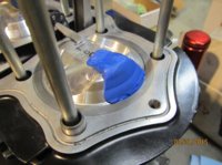
Now I'm checking "squish". I thought the clay method would be best. But I didn't put vaseline on both sides of the clay so now its stuck to the piston. Not only that, this is hobby shop modeling clay. It's very soft. Seems like getting an accurate measurement would be difficult. I think next time I might try solder.
Now I'm checking "squish". I thought the clay method would be best. But I didn't put vaseline on both sides of the clay so now its stuck to the piston. Not only that, this is hobby shop modeling clay. It's very soft. Seems like getting an accurate measurement would be difficult. I think next time I might try solder.
Attachments

650performance
XS650 Addict
Putty works well. Personally, I prefer using 1/2" pieces of 1/8" diameter soft solder that I put equidistantly around the piston's edge plus the valve pockets. The solder is hard enough so that you can pick it up and (gently) measure the thickness with good accuracy. I hold the solder in place with putty or a dab of thick grease.
I began checking the piston on four sides when I discovered that the clearance readings around the piston weren't always the same when coupled with heads that featured modified combustion chambers (who knows where it had been touched with the rotary grinder). This way I can ensure I don't get the squish any closer than .035" on any axis of the piston.
I began checking the piston on four sides when I discovered that the clearance readings around the piston weren't always the same when coupled with heads that featured modified combustion chambers (who knows where it had been touched with the rotary grinder). This way I can ensure I don't get the squish any closer than .035" on any axis of the piston.
I did not put it in the exhaust for the picture but thought that would be a given. I leave the putty in there and measure with out removing. Used the pointed end of your caliper that way there is not distortion or any error. (at least for me). The picture is just a reference for you not and actual reading. the other pic is to show easy clean up with putty.
Attachments


Last edited:
Champion750
XS650 Addict
Ok so I decided to try using solder to check squish and it seemed to work pretty well. The solder I used is .090" thick. The head gasket I'm using for this test is .042" thick. I don't know the thickness of the base gasket, I forgot to measure it. (I still can but I doubt I'd change it whatever it ended up being).
At first I held a piece of solder down in the spark plug hole just to test it out and brought the piston around past tdc. Then I placed four pieces on both pistons as in the pics to get a final measurement.
The smallest measurement I got is .035". This seems like it's right at the limit for clearance. The area where this measurement is taken is right at the outer edge or corner of the combustion chamber. I guess to be accurate I should measure the deck height of the pistons too.
The question of the day is: should I run it with this head gasket or play it safe and go with a thicker head gasket?
Any input would be helpful, thanks.
Attachments


650performance
XS650 Addict
If the .042" head gasket head gasket is used/already compressed and you used at least a few pounds of torque on the head bolts, then you should be good vis-a-vis the .035" minimum spec. If you want to be absolutely sure, then also measure the fore and aft squish (i.e. 90 degrees to where it is in the pictures). I've discovered that the squish area by the EX valve sometime tends to be a few thou closer than on the other quadrants.
Looking good.
Looking good.
Champion750
XS650 Addict
So after thinking about it I decided to play it safe and use the thicker head gasket in the final build. That would be the XS Performance 'fiber' gasket that is .063" thick. This will increase clearance by about .020" over the copper one I used when measuring squish. This is my first build with this engine and I need a baseline to go off of so it doesn't need to be just right yet.
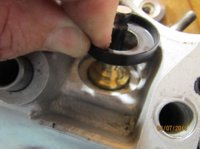
Now I've noticed something that puzzles me a little. The pics show the valve spring cups that came with the Megacycle cam I had ground and I noticed the cup doesn't rest on the cylinder head itself when installed. It rests on the valve guide which spaces it up off the head surface by about 1/8" (a little hard to see in the pics). Maybe I'm wrong but this doesn't seem right. I would think the cup would bend from continuous valve spring pressure.
Do I need to open up the center hole in the cup so that it rests down on the head surface?
Attachments

If they are RD springs, to get the required spring height you will need to open the center hole so it sits the stock shim. If you were running a low lift cam like the Shell #1 you could just use them put them in on top of the collar. But for a cam with higher lift like the 250-30 you will end up with coil bind if you do not modify the hole. Call if you have any questions or I did not explain clearly. Gary
563-940-3363o
563-940-3363o
The RD's (which megacycle sells) are suppose to sit on the step and not on the shim. If you just add the shim it will be lower then the step. so you have to make the hole so it fits over the step. and then it can sit on the shim. I have done lot of these. When I send out spring sets I modify the cup it I know what cam you are running. Gary
Similar threads
- Replies
- 46
- Views
- 6K