Since it passes the "slap" test, it appears the alternator is powering up. That would also indicate the regulator is sending power to it to make it do so. The problem could be with the rectifier. That's what changes the AC current created by the alternator to DC and delivers it to the bike's battery and electrical system. That would be my next check. I've found several bad ones in the past. The issue was usually melted wires or the plug. Don't know what caused it, bad ground maybe.
-
Enjoy XS650.com? Consider making a donation to help support the site.
XS650.com receives a small share of sales from some links on this page, but direct donations have a much greater impact on keeping this site going.
You are using an out of date browser. It may not display this or other websites correctly.
You should upgrade or use an alternative browser.
You should upgrade or use an alternative browser.
How do I test my stock alternator
- Thread starter 79josh81
- Start date
79josh81
XS650 Addict
so heres what I've found so far:
My battery voltage is 12.54v. I measured voltage at the key switch (going into the switch and out with the key on) and it's 12.4v, so no issue there. I went down to the brushes and voltage was only 11.5v with the key on. So I pulled the brushes, cleaned up all of the contacts, screws, etc. Brush length is fine. Before I put the brushes back in, I tested the voltage (with the key switch on) to the positive to the brush and I had the same voltage as the switch now...12.4v.
So I'm like "good", I put the brushes back in a retested the voltage on the same positive wire going to the brush while they were in. It was 11.5v again. WTF. So I took it out and tested the wire again without the brushes in...12.4v. Cleaned everything some more, put the brushes in, tested the voltage again at the brushes...11.5v. I think it's just the way I tested with it out and with the brushes in maybe????? I was able to test the inside of the ring lug connector to the brush when it was out, and obviously had to test on the outside of the connector with the brushes in. So maybe thats why I'm seeing a difference.
Last edited:
79josh81
XS650 Addict
Since it passes the "slap" test, it appears the alternator is powering up. That would also indicate the regulator is sending power to it to make it do so. The problem could be with the rectifier. That's what changes the AC current created by the alternator to DC and delivers it to the bike's battery and electrical system. That would be my next check. I've found several bad ones in the past. The issue was usually melted wires or the plug. Don't know what caused it, bad ground maybe.
I'm going to keep going to the steps and I'll get there soon.
You should do this. With the brushes out, check resistance of each slip ring to a good ground. This will show you if there is a short to ground in the rotor, sometimes this short can be intermittent and hard to verify that it is happening.
Scott
Scott
Last edited:
79josh81
XS650 Addict
Here are test procedures for testing rectifier. Do you have a manual?
I'm going to be honest, I don't know how to read that chart. But I do have instructions in the haynes manual for testing the resistance from the rectifier in ohms. When I unplugged the rectifier, I tested the plug end of the rectifier in ohms (tested each 3-white wires to the black and then each 3-white wires to the red wire). The only thing my digital multimeter does is show me 1 in the left of the screen. The only way I was able to get any sort of reading was setting the ohms to 2000k and then a couple combinations of tests read in the 300's.
If I understand multimeters right (in the week I've been using them), the 1 in the left means theres no continuity at the range that I set on the multimeter. Considering I then set the range up to 2000k, and then started getting some spurratic high readings, I'm assuming my rectifier is recti-f*cked. Unless I'm an idiot. Either way, everyone chime in and set me straight please.
79josh81
XS650 Addict
79josh81
XS650 Addict
A rectifier is a set of six diodes. A diode is a one way valve. Power flows one way with very little resistance, the opposite way it has very much resistance so power can't flow.
That chart shows the diodes and how they are interconnected inside the rectifier.
The test procedure tests each diode forward and backward.
You hook the red test lead to the positive wire and use the black test lead to check the resistance at all the white wires. Write down the readings.
Now reverse the set up Black lead on the red wire Red lead to each white wire. Write down the readings.
At this point you should have one set of low readings and one set of high readings.
Now repeat these test using the black rectifier wire. Again you should get a set of high readings and a low set.
The low set of readings is the forward flow of the diodes, the high readings are the backward flow readings.
As you look at the diagram of the rectifier the diodes kinda look like an arrow. The arrow points the direction of flow.
The red wire hooks to one end of the diodes The white wires hook between the diodes, the black wire to the other end of the diodes.
AC swings from a positive voltage to a negative voltage as it cycles. As the AC flows to the rectifier the positive half of the cycle flows one way through half of the diode and the negative half of the cycle flows through the other half of the diodes. As the AC swaps polarity the power flow reverses through the diodes.
This only lets DC flow out the red and black wires. Red the positive side, the black the negative side.
In the element ok column if each diode has a low reading one way and a high reading the other they are ok.
If your testing shows a bad diode in the rectifier you need ta new rectifier.
Ebay has lots of 3 phase rectifiers for noit much money.
Leo
Ohms setting should be on the lowest setting as in the second pic. Can use the 200K at a pinch but the 2000k should be used
79josh81
XS650 Addict
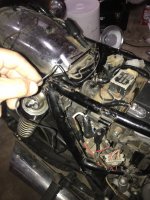
View attachment 126090 View attachment 126089 View attachment 126088 I FIGURED IT OUT*****
So I cleaned the rectifier after I had it off and thought well maybe I should plug it in at the side of the bike (instead of completely reinstalling it) and test the battery voltage again. So I plugged it into the plug and then took a alligator clip jumper and attached it to the ground of the rectifier and then attached the other side to where the battery grounds to the frame under the seat.
I started the bike up, got my multimeter on the battery and throttled up. It worked! My voltage climbed from 12.5 all the way into the mid-14v’s. I’m like oh, the ground on the rectifier was shit.
So I cleaned it up all pretty, reinstalled the rectifier, put the ground loop back on the bolt that goes through the rectifier (and mounts it to the bottom of the battery box), started it back up, and NO CHARGE.
I’m like, ok, the ground underneath the battery box isn’t clean enough then. So instead of pulling the whole rectifier again, I just loosen the nut that holds the ground in place, remove the ground wire loop (while leaving the rectifier still tightened to the bike), I put my jumper on the rectifier ground like I did before and ran that up to the battery’s ground again. I started the bike...and something strange happened...the battery still wouldn’t charge even though it did before with the rectifier grounded with the jumper.
At this point I’m like what the f*ck. So I remove the rectifier so it’s not attached to the battery box and is just hanging by the wires underneath it not touching anything, I still leave the jumper on the ground from the rectifier and have it connected to the frame where the battery grounds under the seat like before....
And guess f*cking what?.....
The rectifier starts doing its job again and starts charging the battery.
SOMEONE EXPLAIN THAT.
My only guess is that somehow when the rectifier is attached to the bike it’s shorting the rectifier out somehow. If the ground didn’t have a good connection when I reinstalled it, it SHOULD have then worked when I ran a grounded jumper to it while the rectifier was still attached to the bike. The only time the rectifier sends charge to the battery is when it’s not mounted on the mounting bolt underneath the battery box.
Can anyone who’s smarter than me please tell me what the f*ck is going on? The pictures show what I did to make it work.
The battery box is isolated and is cannot be used as an earth/ground. The Earth/ground goes through the connector/wiring into the loom on the black wire......or run a jumper back to the battery Earth/ground
79josh81
XS650 Addict
79josh81
XS650 Addict
But the problem is is that even if I ground the rectifier up by the battery, when I remount the rectifier to the bike on the mounting bolt, it stops working.Thats what I was saying before. And the ground on the rectifier is so short the only place it could be mounted without running a new wire would be to the rectifier mounting bolt.
Last edited:
!!!....Maybe it is shorting when the bolt is tightened as you think..........Don't know, maybe just buy a 3 phase rectifier to replace the old unit, and go that way. They are cheap enough to buy 2 just in case one is faulty.
Before the 3 phase ones were used we used 2 single phase in tandem with gave us a spare diode to use if by chance one failed
Before the 3 phase ones were used we used 2 single phase in tandem with gave us a spare diode to use if by chance one failed
Maybe the battery box itself isn't grounding properly. Try bolting it in place and running a jumper from the rec. mount bolt to a known good ground.
79josh81
XS650 Addict
Any links to what 3 phase rectifiers I could buy that would work? I’m way out of my comfort zone searching for a rectifier that will work with my stock wiring with the 3-white wires, 1-black, and 1-red.
You're not supposed to remove the rectifier the way you did, by taking the nut off the bottom and pulling the unit off the stud that runs through it. You're supposed to remove the nut on the top inside the battery box under the battery. That stud that runs through the unit is what holds it all together and there were probably insulating washers between the different layers. They may have fallen out now so when you bolt the unit back on, it shorts out.
79josh81
XS650 Addict
That’s something I could try Jim.
79josh81
XS650 Addict
Well I didn’t lose any insulating washers. I know that for sure because there wasn’t any on there to begin with. It looks like whoever had the bike before me replaced the rectifier because the words “$40 - Yamaha xs650” is written on the side of the rectifier with a paint pen. Maybe the dip shit before me replaced the rectifier and lost some sort of insulating washers and that’s why it’s not working. ???
Anyhow, what’s my next move guys?
Anyhow, what’s my next move guys?
Similar threads
- Replies
- 9
- Views
- 2K
- Replies
- 28
- Views
- 2K