-
Enjoy XS650.com? Consider making a donation to help support the site.
XS650.com receives a small share of sales from some links on this page, but direct donations have a much greater impact on keeping this site going.
You are using an out of date browser. It may not display this or other websites correctly.
You should upgrade or use an alternative browser.
You should upgrade or use an alternative browser.
How does this look?
- Thread starter franklinshaw
- Start date
-
- Tags
- bobber chopper electrical
franklinshaw
What just happened??
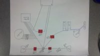
srry its upside down.. ill fix it when I get home
franklinshaw
What just happened??
a question to go with.. can the condenser be mounted in a mock up oil tank or does it need to be in air flow?
franklinshaw
What just happened??
The condenser does not need air flow.
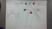
I revised your sketch a little. I think you want a headlight switch, to have the headlight off when you are starting................optional. Also, you did not show wiring for the tail light. Load fuses are normally 10 amp.
I revised your sketch a little. I think you want a headlight switch, to have the headlight off when you are starting................optional. Also, you did not show wiring for the tail light. Load fuses are normally 10 amp.
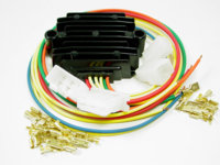
Attachments
franklinshaw
What just happened??
That's awesome thank u so much. I have a question tho. My tail light only has two wires coming from it.. Is there something im not seeing?
4stroke
4stroke
im pretty sure one goes to hot before switch for running light and one is after switch please correct me if im wrong cause i plan on running this same set up without kick start
4stroke
4stroke
how is this set up different from running a pamco?
jayel
#9 Guru 74 TX650A
That's awesome thank u so much. I have a question tho. My tail light only has two wires coming from it.. Is there something im not seeing?
one wire is the brake light the other the tail light, the body of the light is the ground for both
how is this set up different from running a pamco?
it isn't the Pamco or any ignition has nothing to do with the tail/brake light circuit
That's awesome thank u so much. I have a question tho. My tail light only has two wires coming from it.. Is there something im not seeing?
Don't forget, just about everything on these bikes is rubber mounted (can't figure out why
 ). Its not like a car, where you can just run the ground from a light to the closest piece of metal. Yamaha had a common ground wire running through the harness, and then grounded that wire at a good bare metal ground on the frame.
Run a ground wire from the tail light body, along the fender and either connect to a known common ground wire or to bare metal ground on the frame.
franklinshaw
What just happened??
so one common ground wire will work throughout all the grounds in the bike? If so will a 16 gauge wire be sufficient? And if the black ground wire from the stator to the reg/rec are connected do they both need a separate ground for each one?
so one common ground wire will work throughout all the grounds in the bike? If so will a 16 gauge wire be sufficient? And if the black ground wire from the stator to the reg/rec are connected do they both need a separate ground for each one?
I'm not sure how exactly Yamaha ran the commong ground wire(s). If I was wiring from scratch, I would run one ground wire from the headlight bucket, to connect all the grounds in that area. Then I would run another ground wire from the rear tail light area. Those 2 grounds wires, I would take them to the same connection point under the tank, and connect them to bare metal on the frame. Yes, 16 gauge should be sufficient.
The ground brush (at the alternator), is grounded through its mounting screws into the stator frame. It also has a black wire that runs out to the common ground wire in the harness. The rec/reg needs one black wire to run out to the common black wire in the harness. So, there ends up being a black wire from the alternator brush to the rec/reg. That same wire will be grounded to the frame under the tank. In addition, the one brush is grounded through its screws.
You can't have too many grounds...............they are important, especially since many parts on the bike are rubber mounted..
jayel
#9 Guru 74 TX650A
since the horn and starter button ground thru the handlebars (rubber mounted) most of these had a black grounding wire from the left switch into the headlight shell, the front fork itself is a poor ground as it's only contact points are thru the fork stem bearings or the clutch and throttle cables, this is why a ground wire back from anything on the front fork (turn signals, horn, starter button and headlight) to a good solid frame ground is important, then we get to the previously mentioned rubber mounted rear fender again a good ground is needed, I like to run grounds to the same point that the battery frame ground uses as stated "You can't have too many grounds"
franklinshaw
What just happened??
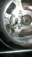
got ya. my three screws that are grounding the alternator brush are nylon. and does the wiring need to be grounded to the frame or can i run all the grounding to the negative side of the batt thats grounded to the frame its self?
franklinshaw
What just happened??
got ya. my three screws that are grounding the alternator brush are nylon. and does the wiring need to be grounded to the frame or can i run all the grounding to the negative side of the batt thats grounded to the frame its self?
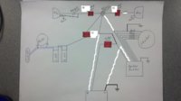
I'm getting confused here. Why do you have nylon screws on one brush? Your original wiring sketch shows 2 ignition coils, so from that I assumed your engine is a 1970 to 1979. With that engine you do not use nylon screws on one brush. I revised your wiring sketch to suit the 70 to 79 type of alternator and rec/reg.
OK you have to state the facts to clear things up:
What year is your engine and alternator?
Which rec/reg do you have..................is it 80 to 83 type or is it 70 to 79 type?
Who installed the nylon screws?
Do you even know which type of rec/reg you have?
franklinshaw
What just happened??
franklinshaw
What just happened??
jayel
#9 Guru 74 TX650A
got ya. my three screws that are grounding the alternator brush are nylon. and does the wiring need to be grounded to the frame or can i run all the grounding to the negative side of the batt thats grounded to the frame its self?
yes you can but grounding them to the frame side of the cable (same connection electricially) reduces the wires going to the battery post, making it easier to get it out if needed
franklinshaw
What just happened??
Got it! U guys got me wrried bout these nylon screws now tho..
Similar threads
- Replies
- 9
- Views
- 263