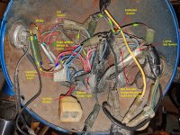
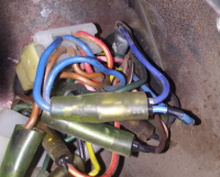
So... if you tie the two blues together at the key sw. it will function just like GLJ says his does.
Pos 1 and power to the tailight will come from the handlebar sw.
Pos II the key sw. will back power the handlebar sw. You can either put a diode between the two switches.... or just remember to turn the headlight off when in pos.II;)
 
Mailman
This is my original harness.
upload_2019-2-24_18-22-4.png

There should be 2 blues coming from the 4 pin connector from the ignition switch. 1 goes to the 2 female bullet connector which the male ends go to the dash lights. The second blue from the 4 pin goes into the main harness also the second blue on the "input" side of the bullet connector goes into the main harness. One of them goes to the tail light, the other goes to the 6 pin going to the headlight switch. When the key is in the 'run" position the red/yellow going to the headlight switch powers the blue to the tail lights. When the ignition switch is in the "park" position the ignition switch feeds the blue. Since the blues are all connected together either the ignition switch or the head light switch can power the taillight. If you have all the blues connected correctly I'm guessing you have a problem in the head light switch. Since you said your head light works that means you are getting power to the headlight switch. It is a bit confusing. Anytime circuits "backfeed" they can be hard to follow.
Something else to check is the blue crimp connectors you have.
upload_2019-2-24_18-44-59.png

Those things are junk on 12 volt DC systems. Working with old wires you are a lot better off soldering the connections.
Edit changed brown to red/yellow
 
Last edited:
So... if you tie the two blues together at the key sw. it will function just like GLJ says his does.
Pos 1 and power to the tailight will come from the handlebar sw.
Pos II the key sw. will back power the handlebar sw. You can either put a diode between the two switches.... or just remember to turn the headlight off when in pos.II;)

Power to the Taillight is a separate circuit so it is powered from position 1 and 2 on the blue wire from the ignition switch.........Edited and added the blue wire info

When reading the XS2 manuals or Owners manual it shows and says, position 2, "only the taillight works"........This can be confusing when looking at the diagram as GLJ states position 2 can also operate the headlight..........
 
Last edited:
Power to the Taillight is a separate circuit so it is powered from position 1 and 2.

When reading the XS2 manuals or Owners manual it shows and says, position 2, "only the taillight works"........This can be confusing when looking at the diagram as GLJ states position 2 can also operate the headlight..........

Maybe what they were referring to ,regarding the tail light, is when the key is in position two, you can get a tailight , but no brake light.
 
Maybe what they were referring to ,regarding the tail light, is when the key is in position two, you can get a tailight , but no brake light.

Yes.

Brake light is operated from position 1, (on), Through the brown wire to the Brake switches then yellow to the brake/stop light


I have not see the inside of the left bar switch.........This is crucial to the diagnostic of the blue wire circuit on position 2 and the lights on/off working in position 2 and relating it back to the wiring diagram
 
Last edited:
Power to the Taillight is a separate circuit so it is powered from position 1 and 2.
In pos.I it's powered by the blue wire from the headlight sw.
In pos.II it's powered by the blue wire from the key sw.
Here's GLJ's pic. Near as I can tell.....
Note: A.... Plug for key switch.
Note: B.... Headlight switch and speedo lights plug in here.
Note: C.... This wire goes into main harness and back to tailight
Note: D.... Looks like this wire goes into main harness just for convenience and comes right back out and into the connector at the bottom, which should be the connector for the tachometer.
Doug, if that works for Bob, looks like you need to draw the two blue's at the key switch together.

upload_2019-2-24_18-22-4.png
 
Yes your right............As per the wiring diagram and the key switch Key on the left of the diagram.........So this has been established and is as per the diagram as it is................so just going over and over........

.Cropping parts of something and making statements on the part got me confused ..........

Need to identify and confirm the statement about a brown wire in the left bar switch........if there is one then the diagram is all up the shit ...........if not then ???????
 
So this has been established and is as per the diagram as it is................so just going over and over........
Bob, have a look at your key sw. connector (the switch or harness side) and see if the two blues are coming from the same pin or connected together in any way.
 
Pics showing the ignition 4 wire connector shows there is 2 brown and 2 blue on the loom side of the ignition switch.............All of these pics are in the XS2 wiring diagram thread.........
here is one i Wrote on to use when recreating the 4 wire into 6 for the diagram and tracing the 2 blue and 2 brown.......

Here......................................Shows the 6 pin coupling for the Rev-counter gauge Lights
robin TX IMG_20181016_221939 Skull copy.jpg text.jpg Robin TX IMG_20181016_155923.jpg

From Robin's TX, (rip), and GLJ XS2
GLJ pic1.PNG GLJ pic4.PNG upload_2018-10-10_12-29-10.png Robin TX IMG_20181016_163553.jpg
 
Last edited:
OK... I see where I'm getting confused. Here's Dougs diagram
F1DFAE8A-30C3-4F27-8DC8-1AC63F5E094Ea.jpeg


Here's what I was expecting to see for the blue and brown if they're connected...

vv.jpg


I got it now... never mind Bob, the two blues are connected. I think if you wire it the way I marked it on GLJ's pic, it should work.
 
Thank you all for your thoughtful and thorough responses. I intend to follow up on all of your leads as soon as I can get back into the garage. You guys are all so great for taking the time to try and help me figure this out. I will take photos to confirm your suggestions.
Doug when the dust settles on getting my wiring sorted, I will be happy to copy paste anything you think would be helpful to the XS2 wiring thread.
Thanks again everyone! :thumbsup:
More eye appointments tomorrow.
 
OK... I see where I'm getting confused. Here's Dougs diagram
View attachment 135711


Here's what I was expecting to see for the blue and brown if they're connected...

View attachment 135712


I got it now... never mind Bob, the two blues are connected. I think if you wire it the way I marked it on GLJ's pic, it should work.

sometimes it's hard to see the trees for the woods. You was looking at it..........Yea i could redraw the pic like yours.........I just figured where there are 4 wires on one side of a connector and 6 on the other and 2 of those six are the same colour as 2 of those going in it would be obvious that they are running on the same circuit
upload_2019-2-24_18-22-4 copy.jpg
 
I didn't realize it would create so much confusion...........have a look at the original diagram if you think that coupling is confusing, lol
 
Back
Top