Something came in the mail today. I ordered it from China and it took 3 weeks to get here...It's a cheap electronic speedo/tach/odometer/gas level(won't be using that feature)instrument lights all in one dash. The analog meters are dying. Needles swinging all over the place. tired of geaseing cables. It's time to go digital! It was under $30 shipped to the door via Uniformed Federal Employee(mailman). I'll post pics after I get them downloaded. I'll have to slice and dice wires to get it connected. Would have been nice to get connectors with pigtails so one could connect this badboy. No, they give only 1/2 of the molded plastic connector. Local electronic store didn't carry that style so I gotta change the connector to get this instrument wired into the bike. Figure out a way to mount this guy on the SG. All part of making your bike more "YOURS".
-
Enjoy XS650.com? Consider making a donation to help support the site.
XS650.com receives a small share of sales from some links on this page, but direct donations have a much greater impact on keeping this site going.
You are using an out of date browser. It may not display this or other websites correctly.
You should upgrade or use an alternative browser.
You should upgrade or use an alternative browser.
This oughta be interesting.
Maybe the gas gauge could be repurposed, like for temperature, or wallet thickness...
Maybe the gas gauge could be repurposed, like for temperature, or wallet thickness...
Hi all: I just stumbled over this thread and it's very interesting.
I noted the ideas earlier about the hardness of the rockers and exhaust studs and the fact is that the engine oil actually cools the rockers plus they do not get hot enough to affect the heat treatment - but - the exhaust studs could get hot enough. The thing about heat treatment is that it affects different metals differently and so it may be that the studs are a higher carbon content than the erockers and thus more susceptible to hardening over time - plus they likely do run much hotter than the rockers.
I noted the ideas earlier about the hardness of the rockers and exhaust studs and the fact is that the engine oil actually cools the rockers plus they do not get hot enough to affect the heat treatment - but - the exhaust studs could get hot enough. The thing about heat treatment is that it affects different metals differently and so it may be that the studs are a higher carbon content than the erockers and thus more susceptible to hardening over time - plus they likely do run much hotter than the rockers.
Hmmm ....You got me thinking there MaxPete....What does a Hot exhaust valve touch after the seat but the guide and the spring retainer and collers and then the adjusters. Not a lot of cooling untill the oil bath and adjuster/rocker. True there is cooling via the valve seat and guide. Rough life for the exhaust valve....
Yes, and that's why they're often replaced at rebuild time.
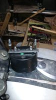
I agree with that!... Onward and upward........ Took off the speedo to see what it's going to take to mount this digital sucker. I think I'm going to look around the Homestore at some square tubeing. See what sizes it comes in. I'm thinking of cutting like a couple 1/2" or so sections and cut a side off to make a "C" of it. Gonna do some slicin' and dicin! Rotory cutting discs on a Dremmel! Sparks a flying tonight! Some drilling too. Off to Lowes!
Ok. Here's the pics


 of the Voltmeter/USB ports...Top pic is of the plate with the threaded rod. There is the top locknut-plate with holes-locknut sandwich. Next is the instaled assembly. Bottom pic is the power source. the brown wire where the turn signal canceler was. It goes to the + side of the USB port and the - side goes to the nut where the turn signal ground. The Voltmeter is in a parallel circiut.
Last edited:
Well, the speedo I have is worthless and a mysterious shorts in the lighting circuit. Sound like time to mount the Digital speedo/tach/dash. Heres some pics.View attachment 106808 View attachment 106809 View attachment 106810 View attachment 106811 View attachment 106812
Well this looks very interesting. I'll be watching closely.
Where did you source the guage? Is it from another motorcycle?
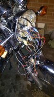
The wire bundle that came with the digital dash had a 9,6 and 3 prong plugs. After looking at what could be used on the dash as compared what the XS 650 can hook up to, is about 12 out of 20 connections. I still have to make a bracket for the speed sensor and the mount for the magnet mount for the wheel. More to come...
Bob, I got this in the mail from China back in April. $25 ordered from ebay. They are about $30 now. No instructions other than what is on the listing and others like it gleamed from ebay.
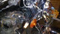
I was busy splicing in connectors,plugs and wires tonight. I'll add pics later. It is late. I had to get my mind off of the tragedy in Las Vegas. My first adopted city after being posted there in '76 and later in '80 at Nellis AFB. Lots of great memories during that time and location.Then this sub human does this evil in my city! Thank goodness he saved us the cost and wasted time of trials and jail and appeals. I blame not his family. Rant over. Here's the pics...I'm making a set of plugs that connect the former Neutral light High beam lights, switched and unswitched power, Rt & Lt signal lights, Tach(off the coil) and whatever connections needed to make the digital dash work. And I think I found the wrong connections that made the short and blew he fuses.
Attachments
Last edited:
A few nights back I put some foam tape in the former Speedometer nacelle to give the new instrument some vibration dampening. Tonight I cut some aluminium bar stock for the mounting of the speed sensor and the magnet for the wheel. I cut some 1/8 thick bar stock to mount the magnet and a section of 1/4 the same shape to back it and space it to the piece with the magnet to the surface of the spoke. It will be held in place with a 6mm diam. bolt and nut. Manet to the outside and bolt to the inside. Here's some pics...


You've put a lot of hours into this gauge project; looking forward to how it all comes out.
Indeed I have. At the time I ordered this gauge, one had to gleam the information of installation from the ebay adds. I recently ordered another one from China for the KZ hybrid project and it will come with a directions. I think it will be worth if for $30. I did save some screenshot of the old adds to help me for now. More to come. I believe it's almost finished.
Well, that's what I did last night. Fitting the magnet on the mag. I don't know if it's close enough to the sensor. I'll find out on the test run or when the when the new Dash comes in with the directions. Also did some wiring changes. On the '80's bikes the RecReg connects behind the air filter. The Alternator connects to the wiring harness between the air filters by the carbs and a short length of harness between the 2 connections. I checked and there is ample room by the carbs and air filter housing for the RecReg and the Alternator to connect without the short length of harness. All I had to do was change the connectors from male to female spades and done. Still needs some zip ties to keep from vibrating too much, but done. Zip tie some more protection to some sharp edges for the frame/body to the harness point to the harness. Do checks to make sure all new connections needed are done and then to calibrating and testing!
I guess a wheel re-balance is in order.
Very inventive and informative.
Very inventive and informative.
bwthor
XS650 Enthusiast
I've got the same gauge, sourced off of Amazon - Even Prime shipping for about $35 - https://www.amazon.com/gp/product/B01J77O0OS/ref=oh_aui_detailpage_o06_s00?ie=UTF8&psc=1
I picked up some extra 1/4" neodymium magnets and put one on each of the six brake disc bolts. They are just magnetized on there for now, but I'm planning to pull the bolts and chuck them up in the lathe and countersink the magnets and paint them. I'm using a small bracket off of one of the brake bolts for the pickup mount. Sorry, no pics yet, but I'll try remember to post some. The trickiest part was getting the speedo calibrated, you have to go in the menu and pick a "frequency" to get it set. If I recall correctly, I'm at about 8.0 with the stock front mag and six magnets.
I picked up some extra 1/4" neodymium magnets and put one on each of the six brake disc bolts. They are just magnetized on there for now, but I'm planning to pull the bolts and chuck them up in the lathe and countersink the magnets and paint them. I'm using a small bracket off of one of the brake bolts for the pickup mount. Sorry, no pics yet, but I'll try remember to post some. The trickiest part was getting the speedo calibrated, you have to go in the menu and pick a "frequency" to get it set. If I recall correctly, I'm at about 8.0 with the stock front mag and six magnets.
Last edited: