some wiring diagrams

On my horns I can't say just what the brand is. They were on the Honda when I bought it.
Harbor Freight has a dual horn set up that sounds a lot like a diesel locomotive horn. About $10. Look a lot like the set on my 75.
On an electric starter you need a starter relay or solenoid. Both the same thing just different names. The starter draws a lot of current. At least 75 amps. You need a starter relay or solenoid that can handle that much current. The stock one works well.
Leo
 
I was thinking about getting those horns from harbor freight too. I bet they don't sound like a moped! I had great ones on my virago and it sounded like a car!
 
Im going to be doing the simplified wiring.... kick only, front and rear lights.
What gauge wiring should I be using

1) from my pma/capacitor/input to fuse holder.
2) from fuse holder to the pamco ignition
3) fuse holder to lights
 
The wire gauges you list are a little on the heavy side, and would make the harness rather bulky and difficult to fit in tight places.

#16 gauge is good for most circuits. #14 gauge can be used for battery to main fuse,main fuse to ignition switch and to rectifier, and ignition switch to the 3 fuses.

Headlight should use #16 gauge. Incadesent 27 watt turn bulbs should use #16 gauge, but LED turn signals can use #18 gauge

Individual circuits such as horn can use #18 gauge. I believe the Pamco ignition uses #20 gauge.

The starter motor cable needs to be large, such as #6 or #8.

I agree with all of your comments as it is in line with what I see on the GS Suzuki's. Most of the issues brought about with wiring are from dirty connections getting the wires hot, not the wires getting hot themselves from the current they are carrying. Of course a heavier wire will draw away more heat from a hot connector, but the source of the heat is generally the dirty connections. With proper connector maintenance you should be able to comfortably run the smaller ga wire you mentioned.

It would seem that there are XS650 loads should be pretty standard and similar to the GS Suzuki s. However one thing that I can't reconcile is why the XS650 uses a 20 amp main fuse. A GS works fine with a 15 amp main fuse. I would gather that the ignition, signal and headlamp circuits are pretty similar in terms of load so why the extra 5 amps on the main?

Is it to do with surge currents from the field controlled alternator? If switching to an aftermarket PMA does it still need a 20 amp main? :confused:

These are the typical currents you see in a GS; the battery charging fuse box arrangement is nearly the same between the two.
Note these are all nominal values, but they are representative of the scope/current clamp measurements I have made.

WIRING_COMPARE_1_zps28b00232.jpg
 
Quite right posplayr.....................its dirty corroded/oxidized connectors that increase resistance and cause heat build up on these old bikes.

The 4 position stock Yamaha fuse panels, which had metal clips and 4 glass fuses, have caused lots of electrical problems. They were OK when new, but as they aged, the clips got weak and the metal ozidized. My finger has felt the heat from the fuse clip to the glass fuse metal end, due to the high resistance.

Its not unusual to fine multi-pin connectors, that have partially melted.

Yamaha used a #19 or maybe its a #18 gauge wire for the headlight circuits. I was doing some work on a friend's 1980 XS650. The Safety Relay was unable to turn the headlight off or on, it was just on all of the time. I found that the switched input and output of the Safety Relay were shorted together, due to melted insulation of the wires (see picture).

Its hard to say what a PO did in order to melt that wiring:shrug: Maybe he ran with the high beam on all the time, but that would only be about 5.2 amps. Maybe he installed a monster headlight with 80 or 90 watts? If the bulb shorted out internally, it should have blown the 10 amp headlight fuse, before it melted the insulation. This is why I recommend #16 gauge wire for the headlight circuit, as compared to the stock #18.
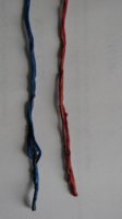
I'm sure a 15 amp main fuse would work on the XS650. I think its just that they came from the factory with the 20 amp and so its been left that way. Also, perhaps the headlight fuse would be better changed from the 10 amp fuse to a 7.5 amp fuse.

I've been using a 7.5 amp fuse (instead of the stock 10 amp fuse) for the ignition circuit, for 3 or 4 years now, as recommended by Pamcopete.
 

Attachments

  • 1980 melted headlight wiring AWG #19.JPG
    1980 melted headlight wiring AWG #19.JPG
    147.2 KB · Views: 139
Quite right posplayr.....................its dirty corroded/oxidized connectors that increase resistance and cause heat build up on these old bikes.

The 4 position stock Yamaha fuse panels, which had metal clips and 4 glass fuses, have caused lots of electrical problems. They were OK when new, but as they aged, the clips got weak and the metal ozidized. My finger has felt the heat from the fuse clip to the glass fuse metal end, due to the high resistance.

Its not unusual to fine multi-pin connectors, that have partially melted.

Yamaha used a #19 or maybe its a #18 gauge wire for the headlight circuits. I was doing some work on a friend's 1980 XS650. The Safety Relay was unable to turn the headlight off or on, it was just on all of the time. I found that the switched input and output of the Safety Relay were shorted together, due to melted insulation of the wires (see picture).

Its hard to say what a PO did in order to melt that wiring:shrug: Maybe he ran with the high beam on all the time, but that would only be about 5.2 amps. Maybe he installed a monster headlight with 80 or 90 watts? If the bulb shorted out internally, it should have blown the 10 amp headlight fuse, before it melted the insulation. This is why I recommend #16 gauge wire for the headlight circuit, as compared to the stock #18.

I'm sure a 15 amp main fuse would work on the XS650. I think its just that they came from the factory with the 20 amp and so its been left that way. Also, perhaps the headlight fuse would be better changed from the 10 amp fuse to a 7.5 amp fuse.

I've been using a 7.5 amp fuse (instead of the stock 10 amp fuse) for the ignition circuit, for 3 or 4 years now, as recommended by Pamcopete.

When you look at schematics like this, you can perhaps see why some people might want to run 14 ga wire on the primary (IGN,SIGNAL,Headlamp) circuits (v.s. 18 ga stock). The 14ga is better able to conduct heat and acts like a heat sink to keep the switches and connectors cooler than say a 18 ga wire. With so few wires , it maybe a consideration especially if you don't want to worry about keeping those switches/contacts clean. This is especially true for the lights/signal devices wires. Either wire can carry the currents without self heating, but the 14ga will keep the switches and connectors cooler.

xs650-1.jpg
[/QUOTE]
 
...Is it to do with surge currents from the field controlled alternator? :confused:

Hey, posplayr, interesting you should bring that up.

I've had this backburner experiment project to implement a diode to shunt the inductive kickback of the exciter/rotor. Last year, a member reported seeing an 'accidentally installed backwards' neutral light LED momentarily light up when ignition was switched off. This indicates that the supply side momentarily goes negative (by at least a few volts) when ignition is switched off, and for a duration long enough to be visible.

Never heard of any reports of this causing a problem, but have been wondering about stress on later model XS650 semiconductor devices, which, for that era, don't like reverse biasing of 5 volts or more.

As far as your 20 amp fuse query goes, if there's enough capacitance on the supply side, could rapidly switching the ignition switch on-off-on induce this extra surge?

You are correct it is no coincidence I mentioned the high fuse value. I suspect the 20A is there for some other reason that steady state current loads. And I would guess that if the main fuses were reduced to 15 amps that they would start to blow under seemingly mysterious circumstances.

As I was designing the SSPB I learned much more than I had envisioned about something called "load dump". This is not something mysterious like the existence of a Sasquatch. It is real and has been to a greater or lessor extent quantified in design standards/test guidelines for electrical transient protection and compatibilities in automotive electrical products.

One such standard that is often quoted is the ISO 7637-1:1990(E) Road vehicles _Electrical disturbance by conduction and coupling . There are specific tests designed to mimic typical transient conditions (i.e. load dump) that can occur in modern alternator based automotive system. As far as I know, these standards have not see the light of day in the motorcycle world, other than the brief mentions I have made in the SSPB design.

On review of the standards and various vendors application notes, I basically designed the SSPB to deal with +100V or -100V transients (10 msec typical), reversed power leads (-14.5v), and working voltage up to +20V (anything above 20V begins to get clamped to ground). These are in addition to the IEC 61000-4-2(ESD) +/-15kV(air) , +/-8kV (contact). Although I have not tested to all these levels the components I'm using are rated to this. I have protection on all input and output connections on the SSPB.

So the simple answer is a -5V transient would be considered mild under ISO 7637 and yes I would worry about newer electronics that are more likely to NOT have such protections built in.

This is one of the more subtle benefits of the SSPB because any electronic/electrical component connected to low impedance power circuits of the SSPB will have the benefits of being in parallel with the Shunt TVS protections in the SSPB.


You can search for the main standard or I can shoot you a copy via email.
 
Last edited:
... I would worry about newer electronics that are more likely to NOT have such protections built in.

This is one of the more subtle benefits of the SSPB because any electronic/electrical component connected to low impedance power circuits of the SSPB will have the benefits of being in parallel with the Shunt TVS protections in the SSPB....

Great, posplayr, you're on top of this! Your SSPB's feature of managing and isolating transients might be able to help save and life-extend the vintage semiconductor components of the later model XS650's.

I've never owned or fooled with these later models, but the array of mysterious failure threads posted in this forum give rise to this line of thinking.

Best wishes on your endeavors...

Thanks for the well wishes. I don't know that the SSPB will solve all of the electrical mysteries in the motorcycle world but I'm hoping it will solve many without adding any of it's own.
 
Finally at the stage where i need to start rewiring. my motorcycle is a 1980 xs650 special 2 from what i believe. i found a diagram that i want to use. my alternator has 3whites 1 brown (looks red) 1 green 1 yellow and 1 blue. now i know the blue is for the neutral and its not showing on the driagram, so does that mean to go ahead cut and toss it? the 3 whites will hook up to the 3 whites on the reg/rec the yellow wire will be caped the green will hook up to the green in the reg/rec the brown wire ( looks red) will hook up to the brown on reg/rec. does that mean that the red in the reg/rec will go to the postive on battery and the black wire from the reg/rec will go on to the negative? on the diagram there is a black wire coming from the alternator except i dont have one althugh there is 1 grey 1 black and 1 orange that i believe are from the brushes, correct? where do does 3 wires hook up too? any help is appreciated thank you all
 

Attachments

  • pic1.jpg
    pic1.jpg
    254.8 KB · Views: 173
  • pic2.jpg
    pic2.jpg
    161.7 KB · Views: 179
  • pic3.jpg
    pic3.jpg
    152.2 KB · Views: 145
  • diagram.jpg
    diagram.jpg
    119.2 KB · Views: 206
The answer to your questions is, yes. the red goes directly to battery positive. the black to good ground or negative on battery. While you are there and wiring, you might want to think about installing a port to the battery for a battery tender. It is a trickle charger that helps maintain the battery in times of non use, like winter. I live in Illinois and I have installed these little easy ports on all of my bikes.
FYI:
Yellow comes from the alternator/stator and goes to a safety relay, which most people just cap off the yellow.
"No harm to wiring harness or system"
The three white wires come from the alternator/stator and goes to voltage regulator and rectifier.
Brown comes from alternator/stator and goes to main switch, fuse box and regulator/rectifier.
Green comes from the alternator/stator and goes to regulator/rectifier.
Blue is the neutral, which again is not necessary.
 
Last edited by a moderator:
Clean all connections with a wire brush or green S.O.S pad, to clean any surface corrosion prior to making your connections.
Make sure to use a good dielectric grease with your connections to ensure good connectivity. The grease also, helps keep moisture out and corrosion because of the lack of moisture.
Double check all wire connections, ensure they are good and tight. Make sure that all connectors that you may crimp on are solid too, pull on wire after crimping to verify solid connection.
I love the guy who invented zip-ties, I use a lot of them. They are great to bundle wires up out of the way of moving parts.
Good Luck, you'll do fine just take your time. No need to rush. Do it all right the first time so, you wont have to keep screwing with it down the road.
 
Are you doing a stock frame or a chopped frame
You should have two plugs coming from your ALT one is for the charging system and the other is for the TCI (black box)
If you are making a harness from scratch and have the old harness just plug in the two from Alt The Reg/Rec plug and the coil and black box and cut them away from stock harness you will have to cut the brown wires the black and blue all the rest will come out attached. If you don't have a setup I do sell them. Make your harness in a couple steps Charging and ignition then do lights brake light horn and switches its much easier.
Any questions you can email me at DADDYGCYCLES@YAHOO.COM
HAVE FUN RICH
 
Man, I wish I had a softail, mine is rigid too. Still though, I wish I wouldn't have hardtailed it. Im getting older and my back is shot!
 
Are you doing a stock frame or a chopped frame
You should have two plugs coming from your ALT one is for the charging system and the other is for the TCI (black box)
If you are making a harness from scratch and have the old harness just plug in the two from Alt The Reg/Rec plug and the coil and black box and cut them away from stock harness you will have to cut the brown wires the black and blue all the rest will come out attached. If you don't have a setup I do sell them. Make your harness in a couple steps Charging and ignition then do lights brake light horn and switches its much easier.
Any questions you can email me at DADDYGCYCLES@YAHOO.COM
HAVE FUN RICH

I noticed your harness sold... You won't have more available till a few months, is that correct?
 
Well, I have had back surgery and I really like the ride on my boulevard. It rides like a Cadillac. On my XS I am using a Large La Pera seat from JP cycles and 4 inch springs mounted. It rides nice, well nicer than it would've been, otherwise. The big seat gives my back and butt plenty of support, and the springs help take the bumps out from the crappy roads. Better than hard mounting the seat. Oh, by the way those spring over shocks for seats are rated to 300lbs. each. So it's like sitting on a 2x4 board. I bought some and tried them. Yeah, waste of money, there is NO give to them. Besides the springs from JP cycles were super cheap too; in price that is. The quality is superior. And they showed up at the house in two days. Fast shipping
 
Back
Top