some wiring diagrams

This wiring is gonna drive me nuts!!!......trying to figure what I need and get it all mounted. I have looked through 33 pages of wiring diagrams and just got more confused. I want this thing to be simple. Here is what I have in mind.

No starter
No turn signals
No horn

What I know I think i need
Battery
Fuse between battery and ign switch
Ignition switch
Headlight
Tail light
Stop light switches
Kill switch
Coils
Points/condenser


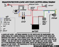
Here is what I am confused about. Voltage regulated/rectifier. I know what one is my regulator. But what one is the rectifier? Will the vr115 replace both of these?

I have ordered a chopper wiring harness from mikes...19-0411

What all do I need to mount on my frame. I have the batter mount and the ign switch mount taken care of.
 
Page 1: The first 6 wiring diagrams all relate to your question. No starter, no turn signals or horn.

Did you read the links i posted in you thread, "what is it" They cover the question about the regulator and rectifier, And read the NOTE: i posted You were told what parts were what in the pics

DADDYCYCLES, (member), makes them up always seems to have a few on hand
 
Page 1: The first 6 wiring diagrams all relate to your question. No starter, no turn signals or horn.

Did you read the links i posted in you thread, "what is it" They cover the question about the regulator and rectifier, And read the NOTE: i posted You were told what parts were what in the pics

I guess I still have not found my rectifier. Sounds like it may still be on my battery box. I think I am understanding it now. The rectifier appears to have battery voltage all the time but the voltage regulator will be switched by the ignition switch.
 
Pic in post 9 of your "what is it" thread... Clockwise............ Regulator, Safety relay, rectifier, starter solenoid. XSLeo answered this question in your other thread.

shawn00sa, you have 2 threads going and then this. It is easier to keep everything in one thread
 
Last edited:
Not reading all the thread and maybe this is a stupid question but WHAT YEAR IS YOUR BIKE?????
1979 to 1983 Single reg/rec on down tube back of motor (ONE PIECE)
1979 to 1970 Two piece REG/REC both attached to battery box and look like this.
 

Attachments

  • 2014-03-27 09.35.39.jpg
    2014-03-27 09.35.39.jpg
    224 KB · Views: 198
It's stupid to post all the information given in the other 2 threads again here. Pics of, and all the questions about the electrical parts in the pics have been answered there, and in my previous post again.

Has the model in his signature
 
Do you have the Clymer's book?
On page 215 is the wiring diagram for the XS1 and XS1B. This is the years before the e-start. A diagram can't get much simpler.
On page 38 they are talking about the charging system. It has a diagram that shows the alternator, brushes, regulator, rectifier. It shows how the wires from the stator go to the rectifier. the brush wires to the regulator.
It also shows how these both hook to the battery and the rest of the electrical system, listed as Load.
The charging system is the most important part of the electrical system. Without it your bike won't run well or very long.
Get this part right and you have it 3/4 whipped. Once you get to the main switch adding the rest of the system is easy. Just add a fuse and run wire to what you want to run. Good grounds and they work.
Leo
 
I got my bike running but not charging,
It's 1978 XS650 with Stock altnator and points , I used my 1980 Reg/Rec as the stock one was missing when i got the bike.

I changed over the screws to the nylon ones wired my bike up as per the nylon screw diagram but it wouldn't charge,
Now what I haven't done is anything with the wires coming from the stator.
Looking at the other diagram I see the brown(/black) wire is set up differntly.
I think i've seen mentioned somewhere that something has to be done with the wires
at the stator is this correct?
I think when I tested it I was getting 12v's on both bush housings.
 

Attachments

  • noid-chopperwiringdiagram.jpg
    noid-chopperwiringdiagram.jpg
    213.1 KB · Views: 216
  • pma.jpg
    pma.jpg
    72.6 KB · Views: 212
so i think i have this figured out for my setup.

-Hugh's PMA
-New Reg/Rect.
-Pamco
-Ultimate Coil
-Sparx Capacitor

What i am curious about is how/where do i wire in the neutral switch and an indicator LED? i can hide the light on the bike quite easily so why not have it, i just do not know how that would tie into this system and function properly. any help would be greatly appreciated.

simplifiedWiring.jpg


I have a 75 that is going to be kick only. Have any luck with this one anyone? I have the huges pma... I saw one on here weeks ago and am kicking myself for not printing it off then, cant find the same one. Just running a head light, tail light...got the capacitor and 2 coils... this one only shows one coil though? will I need 2?
 
Its easy to install but why would you want it if its kick only. You are going to know that its in neutral when you go to kick it. Light is not going to light up until bike is running.
Neutral switch is easy one side goes to hot and the other side goes to motor switch left side under carbs. That's the ground ...

got an example of a diagram? If your referring to my post?
 
Daggy, just realized you weren't talking to me.

On that note, I cant find the diagaram I saw a month or so ago on here? Running kick only, head light, tail light, and that's about it...no indicators etc. Have the Hughs PMA. Anyone have anything that would/may work? I knew I should of printed it off when I first saw it. Greatly appreciate the help...hoping to get a table built and start wiring this weekend.
 
I don't know if you are running pamco but you could follow this and if running stock you just add the stock ignition
 

Attachments

  • xs650-PMA-PAMCO-basic-diagram.jpg
    xs650-PMA-PAMCO-basic-diagram.jpg
    131.7 KB · Views: 283
  • 1981simplifiedwiringpart3.jpg
    1981simplifiedwiringpart3.jpg
    48.8 KB · Views: 209
scrapper, The early bikes regulator sensed battery voltage on the brown wire, if low it sent power to the brushes on the green wire. At the brushes power went through the rotor, out the other brush and grounded to the stator with the three metal screws and to the harness on the black wire.
It controlled the power flow by turning the power on/off.
The later reg/rec, power was sent to the brushes on a brown wire, through the rotor out on the green wire to the reg/rec. It reads the voltage on the brown wire, if low it grounds the green wire. It controls power flow by turning the ground on/off.
Now to convert the early system to use a later reg/rec you need to replace the three metal screw with nylon, this ungrounds the black wire brush. It doesn't remove the ground to the harness.
You need to remove this ground and supply power to this now ungrounded brush.
I do this by tracing the wire bundle up from the stator to the big harness plug. On the harness side of this plug cut the black wire off an inch or so from the plug. This leaves you room to splice a brown wire to the black wire. Run the black wire to your new reg/rec. Splice it to the brown wire at the reg/rec.
Now when you turn on the key power flows to both the brush and the reg/rec.
If your brushes, the rotor and the stator are ok it should charge.
Leo
 
scrapper, ...
I do this by tracing the wire bundle up from the stator to the big harness plug. On the harness side of this plug cut the black wire off an inch or so from the plug. This leaves you room to splice a brown wire to the black wire. Run the black wire to your new reg/rec. Splice it to the brown wire at the reg/rec.
Now when you turn on the key power flows to both the brush and the reg/rec.
If your brushes, the rotor and the stator are ok it should charge.
Leo

Leo, thanks very much for the details, this is what the diagrams you find don't tell you...
I've tweaked the diagrams slightly below as to what I understand you are sayin about splicing thr brown and black, is this correct?
 

Attachments

  • Test.jpg
    Test.jpg
    136.4 KB · Views: 214
  • test2.jpg
    test2.jpg
    82 KB · Views: 228
I found a diagram and tweaked it a little.. can anyone give me some incite if this would work or am I doomed to have failing components.. Just installed a PMA, going kick only. and all my old wires are toast.
 

Attachments

  • 2way.jpg
    2way.jpg
    176.1 KB · Views: 249
Most horns, power is sent to the horn then from the horn to the button where the button grounds. If your button supplies power to the horn then you will need a ground.
Leo
 
Back
Top