Okay, suppose the battery fuse blew, but the one in your diagram remained. Then, the alternator could go into runaway mode and damage the Pamco.
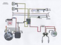
An interesting logic challenge, isn't it? Of all the single-fuse diagrams out there, yours is probably the best. If the fuse blows, the harness and Pamco are protected. And even if the charging system and/or the main red wire cook, you still have a potentially/temporarily field fixable system, allowing you to limp home (by wiring in a temporary battery and running total-loss).
If any condition exists that jeopardizes the ignition system, it gets more troublesome, expensive, and requires being hauled home.
Blowing fuses is not a frequent thing, and most of the bikes here would run fine with unfused electronics. But, it can and does happen, and you want to minimize damage when it does. So, you have to think in terms of cutting the source of damaging electrical power, the battery.
The PMA and Pamco add the twist, as you want NO scenario that allows runaway/unregulated charging voltages to reach the Pamco. Your existing single-fuse diagram handles that.
What's left is that unfused red wire between the battery and charging system, which is actually how most charging systems are wired, so you could leave it as is.
Having worked on a lot of machines that had failed charging systems, ranging from simple/slow battery discharges thru regulators and rectifiers, to full-blown charred remains, I have a natural 'combat fatigue' perspective to that part of the system.
Myself, I would add a fuse in the charging system line, and, something I've not seen elsewhere, the use of a DPST ignition switch, connecting the battery to the main ignition line, and separately, to the charging system, each line fused.
But, that's my 2 cents. Your diagram will work fine. The important part is that you can see the logic of your wiring design, and account for all scenarios...