I did a search in the archives and couldn't find anything on the very basic wiring for LED turn signals. I took my original turn signals off (they all worked) and replaced them with a set of LED's and replaced the flasher to an LED flasher (LF1-S-flat) from superbrightleds.com as recommended on this site. But now I have nothing--no flashing or no light at all from the signals. Here's my question---the original turn signals have 1 wire--red (I think is power) and another wire coming from harness to the turn signal with a rounded ferrell for the ground at where it's mounted. With the LED's--there are 2 wires coming from the turnsignal--1 red (power) & 1 black (ground?) which I didn't use because I used the original ground wire from the wiring harness as the ground on the mount. Should I have connected these two wires directly? Thanks in advance for any help
-
Enjoy XS650.com? Consider making a donation to help support the site.
XS650.com receives a small share of sales from some links on this page, but direct donations have a much greater impact on keeping this site going.
You are using an out of date browser. It may not display this or other websites correctly.
You should upgrade or use an alternative browser.
You should upgrade or use an alternative browser.
Very basic LED turn signal wiring question
- Thread starter DanW
- Start date
-
- Tags
- electrical
HooliganCycles
XS650 Addict
I think you either need to hook up the black wire from the light to ground, or of your flasher is a two prong and it is plugged into the stock flasher plug you may need to plug it into the other slot, if that makes any sense, the original flasher had three prongs and one was for the self canceling, if one of the prongs from your new flasher is plugged into the slot for the canceller your lights won't come on, I am going thru similar led problems right now and when I plugged my flasher in nothing happened, I moved it to the other slot and they came one but didn't flash, I also think the flasher needs to be about a foot away from your coil cuz it will pick up interference and not work properly... Hope that helps and maybe some one will come along with a better idea, good luck
I have a '72 xs650 which uses a 2 prong flasher--so when I got the LED flasher (2 prong) I tried both ways and still nothing--and it is away from the coil. I just noticed the other link with LED turn signal problems as well but no mention on the turn signal wiring. I'm fairly sure that's where my problem is.
HooliganCycles
XS650 Addict
I think your right, so the black wire coming out of the LEDs you did not hook up, right? I would assume that is the ground, and the stock ground wire you hooked to the base of the light? Like the stock one? I think that black wire from the light needs to go to a good ground, I belive the stock ones ground thru the housing on the light where the ground for the LEDs is wired inside the unit and needs to be ground.... Hope that help... Or made any sense at all
So I connected the black wire from the turn signals directly to the dedicated black wire that originally grounded at the mount and now when I flick the turn signal switch left or right---all turn signals flash at the same time like I have hazards on. I'm out of ideas now.
HooliganCycles
XS650 Addict
There is a post on here somewhere that talks about the early bikes doin that, I think it had something to do with the indicator light up at the handle bars, I will try to find it again and post a link If I find it
jayel
#9 Guru 74 TX650A
So I connected the black wire from the turn signals directly to the dedicated black wire that originally grounded at the mount and now when I flick the turn signal switch left or right---all turn signals flash at the same time like I have hazards on. I'm out of ideas now.
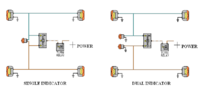
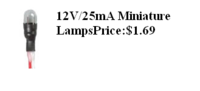
if you have a single bulb turn indicator it will do that as it uses the other side turn signals as ground this wiring diagram may help explain it... solution is to get two (radio shack)12 volt mini bulbs and put both into your single socket
Attachments
Hombre Verde
TheDynamicCycles.com
The black wires from the the LED's are a ground and must be grounded. Black from your harness should be a ground also. Maybe try grounding the LED's to their own frame ground. Not sure what else they are grounded to as I just chucked my original harness and started from scratch. Never spent any time figuring it out.
I bought a 3 prong flasher from AutoZone that stated it was for LED turn signals. I cant remember the make or model but it is right in the flasher section. It was twice as much as a normal flasher, $15 or so. One wire is a ground, one is the power wire and the other is to the turn signal switch. I also rewired the entire bike so not sure how the original wiring works but this is how I did it.
[/IMG]
I initially wired the turn dash signal indicator light to the left and right turn signal wire after it came from the turn signal switch which when I turned on either signal they all would come on and not flash. Then changed it to what you see above and it works great now.
Attachments

Last edited:
ippytattoo
Just another grumpy old hack.
Another way to do it if you are familiar with electronics is by using 2 diodes like I did, the diodes allow electricity to travel in only 1 direction.
jayel
#9 Guru 74 TX650A
Jayel--I think I do have a single bulb indicator that is in the tachometer so....how would I go about getting two bulbs into one socket? Is there another socket that is empty in there?
those mini bulbs are small enough two will fit up inside where the one is now, one will flash for right side one for left... wire them like the right hand side of wiring diagram, left side is single bulb wiring
coughing skunk
XS650 Addict
Another way to do it if you are familiar with electronics is by using 2 diodes like I did, the diodes allow electricity to travel in only 1 direction.
I would also suggest this method. All you'd have to do is buy two diodes (http://www.radioshack.com/product/index.jsp?productId=12681238 $0.60 each) and wire them as shown in ippytattoo's diagram.
No need to buy another bulb and fuss with the indicator light.
Hombre Verde
TheDynamicCycles.com

jayel
#9 Guru 74 TX650A
Wiring is for a single indicator light. As long as you use the wire from the flasher your indicator light will flash when either signal is flashing with out the use of diodes.
[/IMG]
yes this would work and be a cleaner work around
Attachments

Well I guess my basic wiring question isn't so basic. Thanks everyone for their help and the different diagrams. This coming weekend I plan on tearing into the tach to figure out the indicator wiring and go from there. Thanks again everyone!
Hombre Verde
TheDynamicCycles.com
Wiring is for a single indicator light. As long as you use the wire from the flasher your indicator light will flash when either signal is flashing with out the use of diodes.
[/IMG]
While reading all the other posts on this I decided to look at mine a little more closely. I realized that what I posted does work but I think the the indicator light stays on and only flashes when you turn on a signal. Didn't notice at first as I was just happy it flashed. I might try the diodes not sure if I want to pull it apart again.
Attachments
Last edited:
Coughing Skunk--
If you're still out there--I added the two diodes you prescribed from radio shack and the LED turn signals now work perfect but..... the turn signal indicator doesn't work now and I checked the bulb and its fine. I also attached the diodes both ways (not knowing if there is there is any direction to them) and still no difference. Have any suggestions?
If you're still out there--I added the two diodes you prescribed from radio shack and the LED turn signals now work perfect but..... the turn signal indicator doesn't work now and I checked the bulb and its fine. I also attached the diodes both ways (not knowing if there is there is any direction to them) and still no difference. Have any suggestions?
speez
XS650 Addict
the signal bulb system works on feedback throu the bulbs that aren't flashing example: right side is flashing (+) the left side is off so throu the bulb (filiment) is giving a ground to the indicator bulb, the leds work with 2 volts so they put in resistores to make them 12v, so the feedback is on resistonce and can't light up the dash bulb, but to fix the problem is very easy, ground 1 side of the indicatore to ground and take your diodes and put the stripe side (cathode) together and conect it to the bulb now your left with the other side of the diodes (anode) those go to left and right signal outputs,i hope this makes sense to you, sorry, that i can't download any pics have no clue how to
Thanks for helping me out Speez! Yea --posting pics on this site is like figuring out a rubiks cube. So if I understand you correctly--the 2 wires going to the indicator bulb (brown & green)--one of them gets a ground wire "T'd" into it? Then the diodes (which do have a directional difference) should have the stripe side facing the indicator bulb on each wire (brown & green)?
Similar threads
- Replies
- 7
- Views
- 171
- Replies
- 20
- Views
- 2K