Apologies - another electrical question :(

h8monday

XS650 Member
Messages
10
Reaction score
1
Points
3
Location
Oregon
I truly apologize for yet another electrical question. I have gone through more old posts than I can imagine to include Curly's diagnostics and I am absolutely stumped. So here's the situation...

78 XS650 complete cafe build
- Hand made minimized wiring harness.
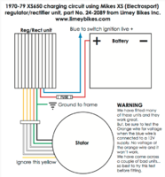
- New Mikes XS combo regulator rectifier x 2 (both ohm test good).
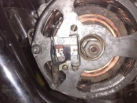
- Rotor 5 ohms between rings - infinity to ground
- Stator tests good.
- New brushes
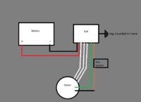
- Brown wire to keyed power source with battery voltage to brush
- Red wire to battery + with 20A fuse
- Black wire to battery -
- 3 white wires to stator wires
- Green wire to green wire
- Inner brush isolated with nylon screws.

Won't charge despite all being good. No magnetism at rotor with key on hooked up the way it's supposed to be.

Strong magnetism and will charge when regulator bypassed (green wire to ground), but voltage climbs > 16 volts with increased RPM as expected with regulator bypassed. (Step 3 of Curly's instructions).

Thought it may be R/R not being properly grounded because of where I mounted it (plastic rear inner fender splash/mud guard). Sanded down a mounting hole on the unit and ran ground wire from bolt/unit directly to battery ground, but still no joy.

Not sure where to go next. I went ahead and put metal screws back in the inner brush and it pops the main fuse (20A on red wire) when I turn the key on. No such thing with the nylons.

I can't get past step 3 on the diagnostics with either of the R/R units. Again no magnetism with key on unless jumped green wire to ground.

Again, sorry for the rehash and any help or thoughts would be greatly appreciated.
 
Last edited:
Mikes sells a Solid State Combined R/R for points ignition as well as for the TCI ignition.....Did you buy the correct one for your model...........

78 model has points and separate Reg and Rect and shouldn't need to have the brushes isolated if the correct combined R/R was bought
 
Mikes sells a Solid State Combined R/R for points ignition as well as for the TCI ignition.....Did you buy the correct one for your model...........

78 model has points and separate Reg and Rect and shouldn't need to have the brushes isolated if the correct combined R/R was bought

The purchased R/R was listed for the correct years 70 - 79. Should have added that but has a Pamco ignition and no longer running points. Not clear on whether it did or did not need to be isolated with a Pamco, but when not isolated, it pops the 20 amp fuse. After looking at hundreds of posts and wiring diagrams, I’m taking a break for a few days. I’m thinking I just have the brush wiring wrong somehow. Some of the older posts with color drawings like Limey bikes, no longer match the wiring color on what Mikes is selling.

I guess the next question is would I need the TCI version due to the Pamco?
 
No, you need to re-wire the inner brush like it used to be - grounded all the time. Don't run switched power to it. Just putting the steel screws back in it will ground it, no need for a ground wire. The original black "ground" wire that ran to it wasn't grounding it, it was picking up a ground from it and sending it to the original regulator. Your new combined unit grounds through it's harness plug I believe.
 
No, The pamco has no relation to the Charging system. The 70-79 Reg/rect shouldn't have the brushes isolated,
There has to be a short that is causing the fuse to blow. post up a diagram of the Wire harness. Go through the whole harness and check the grounds/earth.
 
The purchased R/R was listed for the correct years 70 - 79. Should have added that but has a Pamco ignition and no longer running points. Not clear on whether it did or did not need to be isolated with a Pamco, but when not isolated, it pops the 20 amp fuse. After looking at hundreds of posts and wiring diagrams, I’m taking a break for a few days. I’m thinking I just have the brush wiring wrong somehow. Some of the older posts with color drawings like Limey bikes, no longer match the wiring color on what Mikes is selling.

I guess the next question is would I need the TCI version due to the Pamco?

Never... ever join two wires together just because they happen to be the same colour ! Japanese vehicles of this period invariably used green wires for ground or earth whereas European vehicles used Black for Ground . Some manufacturers used Red for positive feeds others used Brown wires !
If you are adding modern or after market parts to these old bikes you must check to see what you are connecting and Never just join colours together.
Obtain a schematic of the internal wiring of your Reg /Rectifier so that you know where each wire is connecting internally and can then connect with confidence

If you don't have a sound understanding of vehicle electrics you really have no business designing and constructing your own wiring looms for your bike. Check to see what you connecting together or you'll fry your components . Sorry if this seems harsh but I really do get exasperated at owners that mess about with electrical wiring without having a basic understanding and a multimeter.

To give us half a chance of helping you please post an electrical schematic or a simple drawing of your wiring loom and we can then see what you might be doing wrong
 
Peanut,

Understand the exasperation and not harsh at all. I do have a multi-meter, know how to use it and not to make excuses, bike had little to no wiring harness when I got it. As for the R/R I followed the directions provided for installing. I know it's unquestionable something stupid that I've done incorrectly here in regard to the regulator rectifier. The wiring harness with the exception of this is solid. As I said, I'm giving it a break for a while after having going through the entire wiring over the last couple days checking everything. Attached is the R/R portion of the wiring. Not so good at drawing these things up and I'm guessing it will be obvious to someone.Lacking in the drawing is the 20A fuse on the red and yellow wire from stator is not being used or shown in drawing.

Appreciate everything so far.
 

Attachments

  • Wiring.jpg
    Wiring.jpg
    32.6 KB · Views: 663
*Update Edit; 29-3-19
http://www.xs650.com/threads/needed-wire-diagram-for-mikes-xs-solid-state-rectifier-regulator.6564/
The thread above was used. ....Post from the PM conversation about this issue
24-6-2018

h8monday XS650 Member
Just an update and thanks to everybody the problem is solved. Got home late last night and jumped on it first thing this morning. As I suspected from Skulls provided diagram, I had power going to both brushes. Grounded the appropriate brush and voila things charging with no problems. Serious thank you to everybody. I knew it was something simple and stupid that I did and sure enough, a week of not messing with it and the expertise on the board and all is good.


Interesting read for another thread on a points models wiring in Mikes Part #24-2089 R/R
.......Post #16 has a good wiring diagram.......
http://www.xs650.com/threads/wiring...ier-regulator-not-a-nylon-screw-thread.39575/
 
Last edited:
hey no worries I was just being grumpy lol.

We are all here to help each other and you will find the help and advice you need here believe me.

First of all separate the PAMCO ignition system and the battery charging system in your mind. They are in no way connected in operation.

Looking at your drawing , you need to fit the switch between the battery and the regulator not after the regulator . I suspect that you have wired up the regulator incorrectly but I am unable to download the PDF install guide from Mikesxs to check.
I believe red wire feeds the regulator the regulator then supplies the outer rotor ring (brown wire) and the ground return (green wire ) comes back to the regulator and is pulse grounded by the regulator. You should therefore have both the brown and the green wires isolated at the stator

Depending on the age of your bike there are basically 2x different charging systems.

1979 and before have a separate regulator and rectifier The regulator supplies a pulsed 12v+ to the outer rotor brush and the inner rotor brush is connected directly to ground
With this stock system you must isolate the brown 12v+ supply, at the stator brush assembly so that it is isolated from the stator body and frame. The inner rotor ring ( green wire) is not isolated and connects to ground (frame ) via the stator body .If you still have the stock pre 79 stator fitted, it should have the correct brush assembly for this system .


Now,,,......If you have fitted a late type (post 1980) combined Regulator and Rectifier ,either stock or after-market (ie Mikexs) you WILL need to isolate BOTH the stator brushes from the stator body . This is because the post 80 type of regulator rectifier provides a 12v+ connection to the outer rotor ring and connects the inner rotor ring to ground within the regulator . If you do not isolate both wires at the stator it will simply blow your fuse or if one isn't fitted it will fry your wiring.!
To do this you'll need to use nylon screws to fix both of the wires at the stator brush assembly so that both are completely isolated from both ground or the stator body (which is ground.)

Show us a picture of your brush assembly on the stator and stator connector showing the wiring
 
Last edited:
This thread may help.........

http://www.xs650.com/threads/needed-wire-diagram-for-mikes-xs-solid-state-rectifier-regulator.6564/

Another thread on a points models wiring in Mikes Part #24-2089 R/R
.......Post #16 has a good wiring diagram.......
http://www.xs650.com/threads/wiring...ier-regulator-not-a-nylon-screw-thread.39575/

Thanks for the links. I did happen to read through both of those already, adding to some of the confusion. Different wiring colors in one thread and the M unit in the second complicated it a bit and the wiring diagram doesn't show the black wire off of the stator.
 
hey no worries I was just being grumpy lol.

We are all here to help each other and you will find the help and advice you need here believe me.

First of all separate the PAMCO ignition system and the battery charging system in your mind. They are in no way connected in operation.

Looking at your drawing , you need to fit the switch between the battery and the regulator not after the regulator . I suspect that you have wired up the regulator incorrectly but I am unable to download the PDF install guide from Mikesxs to check.
I believe red wire feeds the regulator the regulator then supplies the outer rotor ring (brown wire) and the ground return (green wire ) comes back to the regulator and is pulse grounded by the regulator. You should therefore have both the brown and the green wires isolated at the stator

Depending on the age of your bike there are basically 2x different charging systems.

1979 and before have a separate regulator and rectifier The regulator supplies a pulsed 12v+ to the outer rotor brush and the inner rotor brush is connected directly to ground
With this stock system you must isolate the brown 12v+ supply, at the stator brush assembly so that it is isolated from the stator body and frame. The inner rotor ring ( green wire) is not isolated and connects to ground (frame ) via the stator body .If you still have the stock pre 79 stator fitted, it should have the correct brush assembly for this system .


Now,,,......If you have fitted a late type (post 1980) combined Regulator and Rectifier ,either stock or after-market (ie Mikexs) you WILL need to isolate BOTH the stator brushes from the stator body . This is because the post 80 type of regulator rectifier provides a 12v+ connection to the outer rotor ring and connects the inner rotor ring to ground within the regulator . If you do not isolate both wires at the stator it will simply blow your fuse or if one isn't fitted it will fry your wiring.!
To do this you'll need to use nylon screws to fix both of the wires at the stator brush assembly so that both are completely isolated from both ground or the stator body (which is ground.)

Show us a picture of your brush assembly on the stator and stator connector showing the wiring

Here's the picture. Not great I know. Nylon screws still in place. The black wire is to the top brush and green wire to the bottom. I didn't have time this morning to snap a pic of the wires, but there are 3 white, 1 yellow, 1 green, 1 black coming off of the stator. There was a blue wire in that cluster for the neutral switch, which is no longer there.

As for directions from Mikes - I haven't been able to download instructions either "too many redirects" and I haven't been able to find other diagrams.
 

Attachments

  • Stator.jpg
    Stator.jpg
    109.6 KB · Views: 270
the 3x white stator wires just connect to the 3x white or yellow wires on the regulator/rectifier in any order so no issues there .

I cannot make out the connections to the brushes as the definition is too low.I see you are using the nylon bolts but I cannot see the isolation clearly

Are you sure that there is no electrical connection between either the black wire or the green wire to the metal of the stator body ?
Try disconnecting the reg/rectifier connector then doing a continuity check between the black wire terminal at the brushes and the stator body . Then do the same with the green wire to the stator body . There should be complete isolation ie no connection .

We really need to see the PDF install guide from Mikesxs because I cannot be sure how this regulator rectifier is supposed to be connected. It could be that the inner brush should be permanently grounded as 5twins says but it all depends on how the regulator rectifier operates and should be wired up
 
Last edited:
the 3x white stator wires just connect to the 3x white or yellow wires on the regulator/rectifier in any order so no issues there .

I cannot make out the connections to the brushes as the definition is too low.I see you are using the nylon bolts but I cannot see the isolation clearly

Are you sure that there is no electrical connection between either the black wire or the green wire to the metal of the stator body ?
Try disconnecting the reg/rectifier connector then doing a continuity check between the black wire terminal at the brushes and the stator body . Then do the same with the green wire to the stator body . There should be complete isolation ie no connection .

We really need to see the PDF install guide from Mikesxs because I cannot be sure how this regulator rectifier is supposed to be connected. It could be that the inner brush should be permanently grounded as 5twins says but it all depends on how the regulator rectifier operates and should be wired up

I checked continuity several times before original posting and everything checks out good. The brush wires have no faults / grounds. Even disconnected the wires at the brushes and tested end to end with no grounds. I’ve gone back over the brushes, mounts and all and no grounds to stator cover.

I’m going to have to shelve this dilemma for a little over a week as I have to head out of town tomorrow for a family emergency. When I get back I’ll dig back in and in the meantime if anyone finds a wiring diagram for Mikes since it can no longer be downloaded, I would be very appreciative.
 
I have used this REG/REC on many bikes and didn't have a problem and just one tip when you are trying to solve a problem with electronic parts you have to break down just the problem you are having. For example you could disconnect everything that does not have anything to do with the charging and just go over that first then add the rest in steps. Sounds like something is crossed and the two guys that are giving you info are the best on here . So take a break read again what they said and start over from the beginning. I know you can do it if you just don't let it get to you. Its a bike that's it. Here are two diagrams I found very easy on line. Mikes XS REG/REC was designed to replace the separate REG/REC on the early bikes . If you are using a 1980 and up REG/REC then the nylon screws are used. I think both of these installs are on here. These guys may be harsh but have years of experience on XS650 and have heard this over and over on wiring.
GOOD LUCK post what you find
 

Attachments

  • rec.png
    rec.png
    208.1 KB · Views: 522
  • reg.jpg
    reg.jpg
    96.1 KB · Views: 1,207
These guys may be harsh

Harsh ??? Moi ??:) ............I'm just a liddle ol pussycat DG .:rolleyes:........

Thanks for posting the diagrams it should be easy to sort it out now I should think.
I think I wrongly thought that it was a 80 onwards RegRec whereas it is a pre 79 and just needs a 12v+ feed to the outer rotor ring and the inner ring taken straight to ground ie the body of the stator but I'd need to have a gander at the diagram to be certain
 
From the diagram that DG has kindly posted it looks like the 24-2089 Regulator rectifier supplied by Mikesxs works in the following way.

A fused 12v+ power supply is taken from the ignition switch (ie switch live) to the reg/rec and connected to the blue wire. (On a stock bike the connection is made to one of the 3x fuses in the fuse block which are live when the ignition is turned on).

The orange wire on the reg/rec is connected to the green wire on the Stator ?? which is isolated from the stator body. This supplies a pulsed 12v+ power supply to the outer ring of the rotor when there is sufficient load on the battery or it is not fully charged . (This is how the regulator turns your charging system on and off.)

The red wire on the reg/rec is connected to the battery positive + This is the 12v+ from the charging system (rotor/stator white wires) to the battery after the rectifier has converted AC to DC . The battery only charges through this circuit when the regulator sends a pulsed 12v supply to the rotor on the green wire.

The two wires I am not sure of their function are the green and orange wires on the reg/rec ? which of these two coloured wires carries the pulsed 12v+ to the green wire on the stator ? If one of these 2x wires is a ground for the reg/rec why then is the rotor grounded via the stator body on the black wire

Can someone kindly go through this post and check that I have got this right please ....I wouldn’t want to unwittingly post misleading or incorrect information.
 
On the '70-'79 system, the rotor is grounded to the stator through the inner brush and it's 3 steel mounting screws. The black wire connected to it doesn't provide the ground but is, in fact, getting a ground from it for the regulator. You actually don't need the black wire connected to the inner brush at all, as long as you instead get a ground for the regulator elsewhere.

On the original set-up and components, the rectifier has a ground wire too. It connects to a ground wire in the main harness, part of the ground wire "circuit" that eventually connects (grounds) to the frame. These new combo reg/rec units only have one ground wire and it gets shared between both the reg and rec inside them. Some say to ground the case too. That may or may not do something, depending on whether the internal components are isolated from the case.
 
If you put a meter on the case and all of its wires and read open circuit it means the case isn't connected to anything.
 
On Mike's #24-2089, the orange wire supplies the 12 volt power to the green brush wire. This serves the purpose of the brown wire on the stock 70-79 regulator.
The brown wire on the bike feeds battery voltage to the reg's blue wire.
The reg reads the battery voltage on this brown/blue wire, if voltage is low it sends full battery voltage out on the orange/green wire to the brush, then the brush feeds this voltage to the rotor, out the rotor on the other brush to ground. This magnetizes the rotor to excite the stator to create juice.
So replace the nylon screws with the steel. Hook the reg's orange wire to the green brush wire. Hook the brown wire from the bike to the blue wire of the reg.
This should make it charge at the proper rate. You have already confirmed the rest of your wiring is right by doing the reg bypass.
Leo

thanks for the confirmation about the 24-2089 operation Leo but which colour wire is it sends the pulsed voltage to the the green stator connection ? is it the orange or green wire ,..or are they both connected inside the reg/ rec ?

I understand from h8mondays posts that the bike doesn't have an original wiring loom or fuse box so the 12v+ supply to the reg/rec should be connected to the ignition switch via a fuse so that it fucntions in the same way that a stock bike does.
 
Back
Top