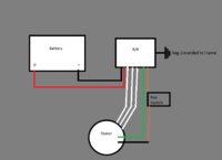
The voltage supplied by the reg on the orange wire hooks to the green wire. This voltage isn't really pulsed it's straight DC just the reg turns it on and off as needed. It may look pulsed on the right test equipment.
Some think this voltage gets reduced to around 6 volts when the battery gets charged, It doesn't, just your meter thinks it does.
The reg turns the current flow on/off. When the battery is low the reg keeps this current flow on longer and your meter reads it as 12 volts. This is the average voltage of the on and off cycles.
As the battery voltage increases the reg turns the current on for shorter intervals and off for longer. The meter reads these cycles as 6 volts, the average of the on/off cycles.
If you hooked an oscilloscope to the reg output to the rotor, you would see these cycles as square waves. When the reg turns on the trace rises to 12 volts for a time, then drops back to zero for a time. The on times show as a fast rise, a flat top and a quick drop. The longer the reg has the current on the longer the flat top, and a shorter flat zero line. As the battery charges the 12 flat top gets shorter and the zero line gets longer.
Leo
")
 .I have just managed to access mikes install guide page and it shows a schematic for a 1981 wiring setup for the pre 79 24-2089?? with presumably isolated stator connections on the brown and green wires but no attached explanation ?