-
Enjoy XS650.com? Consider making a donation to help support the site.
XS650.com receives a small share of sales from some links on this page, but direct donations have a much greater impact on keeping this site going.
You are using an out of date browser. It may not display this or other websites correctly.
You should upgrade or use an alternative browser.
You should upgrade or use an alternative browser.
Generator brushes
- Thread starter royxxx
- Start date
-
- Tags
- electrical
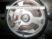
As soon as I connect the #3 screw it blows the fuse, #3 goes into the brass socket that's part of the bakelite base, yes? should there be some sort of insulation? or do you think the problem might be with the winding or something?
Your #3 is the hot from the regulator. Yes it screws into the brass nut in the brush holder.
If the battery voltage drops below the 14.5 preset the regulator sends battery voltage to the brush on that green wire through the brushes and rotor to ground, this energizes the rotor to create the magnetism to excite the stator.
Now the battery voltage is grounding somewhere. Have you checked the rotor for continuity? The rotor should have 5 ohms from slip ring to slip ring and infinity to ground. If your rotor is shorting to ground , that can blow the fuse.
If the bakelite is cracked or broken it may short to ground.
Oh just had a thought, the brushes are different. The hot brush, the one #3 goes into the metal holder is the short one, it just goes from under the screw, up the side of the holder and over the brush.
The ground brush has that plus it goes down the other side under the #2 screw then over under the #1 screw. So it's held by #'s 1,2and 4. If you installed the brushes opposite, you will have the long brush under #'s 1,3,4 instead of under #'s 1,2,4. This will send power to ground on screw #'s 1 and 4.
jayel
#9 Guru 74 TX650A
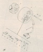
reading this might help
http://650wiki.org/index.php/4.06._Alternator
http://650wiki.org/index.php/4.06._Alternator
Attachments
The #3 screw/wire is ok untill I plug in the regulator, the reg' checks out as spec.
Slip rings have 5.7 ohms between them, but slip rings to casing has continuity.
The three white wires have 1.1 ohms between any two.
Does this mean the rotor is toast?
When I got the bike the battery was cactus, but the bike wasn't blowing fuses.
Slip rings have 5.7 ohms between them, but slip rings to casing has continuity.
The three white wires have 1.1 ohms between any two.
Does this mean the rotor is toast?
When I got the bike the battery was cactus, but the bike wasn't blowing fuses.
You should get no continuity from the slip rings to ground. It you are, thats where the power is going to ground.
Removed the stator, stripped the casing off the wires to check for damage, nada.
The green & black have continuity to each other & the casing.
Rotor has cont' between slip rings & 5.8 ohms, with no cont' to ground.
Prognosis, gents.
Thanks, Roy.
The green & black have continuity to each other & the casing.
Rotor has cont' between slip rings & 5.8 ohms, with no cont' to ground.
Prognosis, gents.
Thanks, Roy.
jayel
#9 Guru 74 TX650A
Removed the stator, stripped the casing off the wires to check for damage, nada.
The green & black have continuity to each other & the casing.
Rotor has cont' between slip rings & 5.8 ohms, with no cont' to ground.
Prognosis, gents.
Thanks, Roy.
sounds like the insulator block is your problem, is it possible you have screws that are to long? going thru block and contacting the alt case? the black wire is grounded so it would show continuity to ground but not to green have you checked it at the plug connector where it goes to the regulator? (unplugged)
Are you using a meter, or a continuity tester? Since the black goes to ground, the green would likely show "continuity" to ground since the rotor resistance is small. Between green and ground or green and black you should see the correct rotor resistance, whatever that is. Plus maybe some brush resistance. Read ohms instead of continuity.
Last edited:
The correct resistances here are so small you need to forget the buzzer and continuity and just look at ohms. 5 ohms is not 0 ohms, but will likely buzz and show continuity just as if it was. Continuity is for checking if a connection is broken and things like that; like you wiggle a wire and if the buzzing is intermittent you know it's a loose wire, for example.
jayel
#9 Guru 74 TX650A
if you are trying to read it with brushes in-place you are reading thru the brush/slip rings/rotor and it will show continuity, it's not a coil yamaha had a bad draftsman on that one
jayel
#9 Guru 74 TX650A
Brushes are removed.
Retested the black/green wires with the meter on 200 ohms, the readings were all 0.6 ohms, are we calling this a dead duck now ?
short your meter leads and see if that reads zero or your .6, meter might not be zeroed
jayel
#9 Guru 74 TX650A
ok so .6 is your zeroI checked the meter probes & yes, 0.6, but this cheap POS has no way to zero.
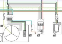
 are you reading 0 or .6 Ω on the green to ground? that green goes to a six connector plug-in then to the regulator might unplug them to make sure it's not shorted in the regulator or along the wire itself
Attachments
Similar threads
- Replies
- 13
- Views
- 450
- Replies
- 18
- Views
- 664