Installing a Vape all in one charging and ignition system.

Quote from the original deutschland seller of the system.

"The original alternator delivers 232W at 5000 rpm. Them consume 42W rotor and controller, as well as the ignition system 52W. There remain, therefore 138W light output. The new system, however PowerDynamo delivers 150W light output.>


The same considerations apply to the stock charging system. The big advantage of the the ac cdi system is no matter how flat the battery is, the bike will make spark.
 
Last edited:
How about the rotors themselves? I notice that they are advertised as being heavier than the earlier systems.
As I've said elsewhere I think these PMA/CDi systems are the best option for the 650. The self powered CDI is the best ignition system on a bike. If it turns it sparks.
 
How about the rotors themselves? I notice that they are advertised as being heavier than the earlier systems.
As I've said elsewhere I think these PMA/CDi systems are the best option for the 650. The self powered CDI is the best ignition system on a bike. If it turns it sparks.
Both 3.2 Lb's, the stock is an inner rotor and the Vape is an outer one. I ran in that situation this summer,had a wire from the regulator break (my fault) which killed the battery, pulled the blue kill switch wire and bike fired right up was good to go.
 
Sorry, been MIA for a bit, had a friend visiting from the great white north.
One thing I'm curious about is the weight of the rotor and stator vs. the stock rotor and stator.

Actually they weight was real close to the same .5.6 lb.the stock one with no wires or mounting hardware , the Vape measured the same.

How about the rotors themselves? I notice that they are advertised as being heavier than the earlier systems.
As I've said elsewhere I think these PMA/CDi systems are the best option for the 650. The self powered CDI is the best ignition system on a bike. If it turns it sparks.
Weighed parts tonight and Gary H is right, weights match, both rotors were the same weight and stators within 1/2 oz. of the factory parts.
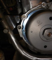
I am more than satisfied with appearance and initial fit up to the engine of rotor and stator.
rotor stator 1.jpg rotor stator.jpg
Removed parts from bags and packing, wiped off the taper ID, with a bit of thinner.
The pin that located the factory stator must be removed.
remove pin.jpg
Installed stator, instructions note and I found that the wire bundle from the stator is a TIGHT fit where it goes under that plate and out towards the grommet at the rear of the cavity.
wire sheath.jpg
I pulled back the sheath and checked no wires crossed each other in the critical close to the crankshaft area, slid the sheath back and installed the stator plate.
wire path.jpg
It fit with close tolerance, no side to side movement, supplied screws with flat washers threaded easily and were of proper length, plenty of threads engaged, they did not bottom. rubber plug at rear cavity partition fit well and trimmed easily to "squishes a bit when fitting cover" depth.
stator on engine.jpg
Manual suggests you can use the stock rubber grommet instead if yours is good.
My crankshaft taper was rusty
rusty taper.jpg
I cleaned it up with 400 grit and mineral spirits.
I cleaned and chased threads on end of crank. The new nut (27mm hex, like the oil drain plugs) was a bit "stiff" to thread on. I cleaned and chased threads then it ran on freely. There are two washers supplied use them both
two washers 1.jpg
The nut turning freely makes the job easier, setting rotor to match timing mark is a bit fussy. If the nut turns hard the crank will spin, (there's no way to keep it from turning) possibly moving the timing as you tighten.
timing marks.jpg
Note; the new rotor does not have a milled keyway, timing is maintained solely with the taper fit and nut tension. To adjust timing; remove nut, loosen rotor with included puller (it works good) rotate rotor on crank, retighten. I'm thinking about how to making the stator adjustable and adding a set of marks to check idle and advanced timing. But that'll be later.
That was it for tonight.
 

Attachments

  • notch in stator.jpg
    notch in stator.jpg
    142.5 KB · Views: 365
Garry to hold the rotor you could make a tool with 2 pins that fit the rotor holes.
I agree it is fiddly getting the rotor in the correct position.
To adjust the stator you could machine the mounting bolt holes into slots, however care will be needed when adjusting not to pinch the wires.
To get extra clearance on a 277 install I relieved the back of the mounting plate.
The join line of the upper and lower cases make a good datum for setup, then you can transfer the marks to the outer cover when the timing is set.
 

Attachments

  • 15b7140962e9b77.32671205.pdf
    714.2 KB · Views: 303
Last edited:
Below is the link to the instructions on how to use the Rotor Tool during installation:
http://www.powerdynamo.biz/eng/parts/grip.htm

May be helpful for those wanting to make their own.

Edit: This articles contains warnings about the use of other tools like oil filter clamps and screwdrivers to hold the rotor due to possible damage to the magnets or coils inside the rotor.
 
Last edited:
Paul, thanks for your input, links, and reference to that tool. It will not stop the crank from moving if the nut does not run smoothly on the threads.
This crank had set for years with no rotor and had some rust, the Vape rotor's fit on the crank is comparable to the fit of a stock rotor. (edited after further testing)
Should be easy enough to devise a pin spanner to hold the rotor.
Thinking out loud, would be nice to be able to adjust base timing without removing the cover.
 
Last edited:
Will be very interesting to hear how those advance curve options work out. Of the four options there is one that retards the ignition slightly and also gives a low advance, I think 5 Degrees, for ease of starting possibly? I shall have to bookmark this thread and keep checking in over the coming months.
 
Yes of the 4 advance schemes possible by setting the dip switches on the black box, one is NOT recommended. The bike Madness would benefit from having a rev limiter.

2019-12-21-06-25-www.vape.eu.png

2019-12-21-06-26-www.vape.eu.png

That last one sounds scary too. May end up with your foot wrapped around your neck kicking with a 24 degree advance. :yikes:
 
Last edited:
This thread is being written as I work, so expect revisions, back tracking, as my understanding (hopefully) increases, methods improve, shortcuts are developed.
I am currently using a spark plug hole stop gauge to get to an accurate TDC but since the rotor is free to move when loosened there is no convenient visible place to permanently mark TDC.
I like to use the TDC marks on the stock system before removing, I will make a mark on the cam and case or if i an doing a complete rebuild i mark the crank gear on the right side.
 
Last edited by a moderator:
Bet I'm not the first to do this and WARNING Vape cautions against hammering on the rotor for fear of damaging, loosening magnets. But I found if I loosen the nut about a turn, and tap the curved edge of the rotor with the handle end of a hammer, the rotor loosens and can be quickly repositioned and nut retightened. Flashlight in the plug hole to find TDC. Hint you have to turn rotor clockwise against the lifter on the cam ramp on the non firing side just a bit to get the top of the piston movement.
 
Bet I'm not the first to do this and WARNING Vape cautions against hammering on the rotor for fear of damaging, loosening magnets. But I found if I loosen the nut about a turn, and tap the curved edge of the rotor with the handle end of a hammer, the rotor loosens and can be quickly repositioned and nut retightened. Flashlight in the plug hole to find TDC. Hint you have to turn rotor clockwise against the lifter on the cam ramp on the non firing side just a bit to get the top of the piston movement.
Is that a precise enough method to determine TDC? I would have thought a piston stop+ a degree wheel, or at least a dial gauge would be required.
On a disassembled engine, I would install the cylinder and pistons, and snugged up the head nuts using some spacers. Put the degree wheel on the primary drive end of the crank, determined TDC, installed the ignition, before continuing with the engine assembly.
Alternatively used the stock timing marks before removing the stock rotor, and somehow found a way to lock the engine in that exact position, then removed the stock rotor, and installed the VAPE.
 
Weighed parts tonight and Gary H is right, weights match, both rotors were the same weight and stators within 1/2 oz. of the factory parts.
That was a surprise to me. Like I stated earlier, the PD/ VAPE for my RD 350 was a lot lighter than the stock alternator and points setup, both rotor and stator. Sorry for assuming it would be similar for the XS, and adding confusion to this excellent thread!
 
Back
Top