New purchase - 1978 xs650E

Small oil leak; check clutch push rod seal (fairly simple DIY repair) and check that the front sprocket nut is tight. 36mm and real tight. Good how to's here on both items.

Use a thin smear of silicone grease on the bullets. Good practise whenever you are going through electrics.
PS hitting multi connectors all over with a bit of rust buster before you try to separate them makes that job go much smoother with less chance of damage.

Lights dim at idle and getting bright as you rev is normal, especially with a 1000 RPM idle. At least one reason for the 1200 idle speed is so you don't pull down the battery idling.

Next up; google head stud re-torque, do not ignore this one. Do it soon, very soon.
 
Thanks, I'll check out the how to's on both those and inspect.

A bit unrelated is that my flashers aren't working on the right side. Inspected all the bulbs and those were fine. Left side flashes fine. Decided to take the left controls apart and I think I found the issue...looks like one of the wires connecting to the flasher control has come unsoldered. Think a touch of solder will fix the issue? (I don't own a soldering iron yet. ..but I suppose I should)

Posted via Mobile
 

Attachments

  • 20140427_174505.jpg
    20140427_174505.jpg
    130.1 KB · Views: 151
Thanks, I'll check out the how to's on both those and inspect.

A bit unrelated is that my flashers aren't working on the right side. Inspected all the bulbs and those were fine. Left side flashes fine. Decided to take the left controls apart and I think I found the issue...looks like one of the wires connecting to the flasher control has come unsoldered. Think a touch of solder will fix the issue? (I don't own a soldering iron yet. ..but I suppose I should)

Posted via Mobile

looks just like the problem i had a while back. yes, a touch of solder will fix it. since you don't have a soldering iron yet, make sure you buy a higher wattage model (40watt or above). that way you only have to keep heat applied for a short time. less prone to melt wire insulation or other plastic bits.

215DED5C.jpg
 
Yes, these switches need to come all apart and be cleaned & lubed. A word of warning here - get some J.I.S. screwdrivers or you'll bugger the Phillips heads all up and never get the switch apart.
 
May not be 100% correct, but I suppose this might work for the reservoir o-ring:

http://www.summitracing.com/parts/rnb-64030/overview/

I measured 45mm outside diameter which is 1.77 inches, or almost 1 3/4 inches by 1.5mm thick which is .059 inches, or almost 1/16 inches. So if using this I'd be off (long) by .55 mm in outside diameter and .0875 (long) mm in thickness.

I'm going to try and reuse mine (don't feel like waiting until a 5/12 ship date), but in case anyone tries to search for the answer in the future this might help provide an option.


edit - or buy a forums worth on e-bay for the same price....

http://www.ebay.com/itm/50-Pcs-Mech...957?pt=LH_DefaultDomain_0&hash=item4ac0d4e25d
 
In need of a little help. Potentially my first ordering snafu. I finally went to rebuild my front master cylinder and had the kit (http://www.mikesxs.net/product/08-0204.html) all laid out and now am realizing the bore on the kits cylinder is 17.5mm.i measured my old m/c and it's 14 mm and from the pictures prior I think pretty safe to say it's the stock m/c (body says Asco 12 on the bottom and as I mentioned, is 14mm. Did I order the wrong part or end up with a mispackaged item? My package number on my rebuild kit matches what was listed online..just want to be sure before I call.

Thanks

Posted via Mobile
 

Attachments

  • 20140501_190329.jpg
    20140501_190329.jpg
    162.4 KB · Views: 143
  • 20140501_190947.jpg
    20140501_190947.jpg
    162.1 KB · Views: 156
  • 20140501_190957.jpg
    20140501_190957.jpg
    169.9 KB · Views: 160
Sorry but you ordered wrong, that kit is for the Dual caliper master cylinder.
Quick Overview

Front Brake Master Cylinder Rebuild Kit - OEM # 1J3-W0041-20 to fit optional Dual Disc on 1980 XS650SG - Master Cylinder - OEM# 2G2-25850-01 & 3J6-25850-00


You need;

http://www.mikesxs.net/product/08-0219.html
Front Brake Master Cylinder Rebuild Kit for Yamaha XS650 + Photo Front Brake Master Cylinder Rebuild Kit - OEM # 535-W0041-60, 535-20000-60
Fits: Front Master Cylinder Assembly on All XS650 Models D-L (1977-84) with
single front disc brake.


Note: This Kit does Not fit earlier 650 models.

Also Fits: XS360 C 76-79, XS400 77-81, SR500 78-82, XS500 76-78,

OEM Reference #
• 535-W0041-60-00
• 535-20000-60

Part #08-0219 $25.50 USD Kit
 
sounds like I'll have a little time to kill, are these Shims needed in rebuilding the brakes or can I do without my new brakes did not come with them

Posted via Mobile
 

Attachments

  • 20140501_195937.jpg
    20140501_195937.jpg
    162.2 KB · Views: 154
Yamaha started using them, but I have never heard the reason. I put them back if they are in good shape, but haven't noticed a difference if I leave em out...............

My guesses are to reduce squeal or to even out pad wear.
 
Few updates for the work this weekend.

After realizing I had the wrong m/c rebuild kit I took the opportunity to order a few clutch push rod seals and some gaskets, along with the copper washer set for the head acorn nuts (along with the right m/c rebuild kit). As a side note, the customer service rep at MikesXs said he'd take the opened package back as a return and responded to an 11pm e-mail at 8:30am the next morning - so good on them (especially some of what I've heard thusfar).

Anyway, I bought a soldering iron and, after cleaning up all my left control connections, soldered that wire back in place. It was a tight spot and I'm not proud of the work, but it seems to have done the trick as I now have both signals working again.

I did, on advice from I believe 5twins, buy a screw driver set wit JIS heads. Not only has it salvaged what I thought were a few toasted screws, but they worked beautifully on the small electronic screws as well - strong recommendation to anyone who doesn't own JIS screwdriver/heads.

Quick cosmetic detour and got a new latch assembly on one of my side covers. Was hell getting the rubber grommet in place but I think it came out pretty good, quality doesn't seem too far off original.

Since I could tell the left hand cover was going to be a mess underneath due to the oil leak I decided to tackle the cleaning today. Fought with the allen bolts for a bit (finally won) and I actually underestimated how gunked up everything was around my sproket. The clutch pushrod actually pulled out stuck to my left hand case; caked in grime and oil and grit. Took about an hour but I was able to get most of the gunk off and back down to a nice, clean(er) surface. On a positive note, I didn't see any signs of oil coming out from the sprocket (I'll still torque it down while I have the case off...just need to buy a new socket), but I'm a little concerned about the bushing behind my clutch pushrod seal. I forgot to buy the bushing along with the seal, but the rod (after cleaning it up) had a bit of play to it. I'm hoping that a new seal with a tighter inside diameter will take care of it, but at least its pretty easy to get at if I have to go back in to change the bushing.

So - Question of the day. Does the chain need to come off to insert the push rod oil seal? Looks like I might be able to hand press it in if I keep the chain on, but doesn't look like I'll be able to get a similar size diameter socket over the seal with the chain in the way.

Anyway, getting closer. Need to torque the sprocket nut, head bolts, replace the oil seal, and get my brakes back together (and register the bike)...but then I should be good to get on the road. Thanks as usual for the help. A few pics...
 

Attachments

  • 20140504_164106.jpg
    20140504_164106.jpg
    83.2 KB · Views: 163
  • 20140504_163346.jpg
    20140504_163346.jpg
    190.7 KB · Views: 159
  • 20140504_163332.jpg
    20140504_163332.jpg
    195.5 KB · Views: 181
  • 20140504_151656.jpg
    20140504_151656.jpg
    276.2 KB · Views: 164
  • 20140504_151646.jpg
    20140504_151646.jpg
    272.5 KB · Views: 184
  • 20140504_150945.jpg
    20140504_150945.jpg
    136.9 KB · Views: 181
It's a lot easier work with the chain and sprocket out of the way. You call that dirty? LOL that was a CLEAN one, and nice work getting it shiny under there.
Yeah those side cover knobs are a bitch to put in.

IMHO the bushing is not a "tight" fit to the shaft even when new, a "bit" of wobble is normal.
 
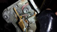
Alright, I'm having some issues with my master cylinder rebuild - fighting and losing.

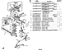
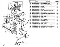
I got the kit suggested above (08-0219) and I can't for the life of me get the snap ring in. I have snap ring pliers, but not master cylinder snap ring pliers. Before either buying some or filing down some cheap hobby pliers, I took some measurements and think something is amiss.

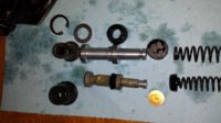
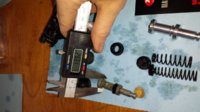
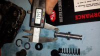
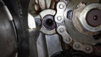
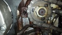
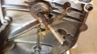
The bore for the cylinder is 14mm+/-, and the piston (plunger?) is basically 14mm. The snap ring and metal washer that came in my kit are 18.5mm. I was under the impression that the washer went between the piston and the snap ring, but given the size the only possible way I could reassemble this would be spring-->cap->plunger->snap ring->metal washer->rubber top hat boot. Given the washer's size, there's no way I could possibly get it into the bore to sit underneath the snap ring (Further down the chamber). My pliers were *just* too short to remove the snap ring, but I was expecting to be able to get the new ring in the bore and then use a pick or something to push it down into its home where it could expand.

Could my snap ring and washer be too large? I don't think I could get that snap ring seated even with the right pliers, it just seems to big. Then there's the washer - shouldn't that be 14mm as well to sit in the bore and press up on the snap ring?

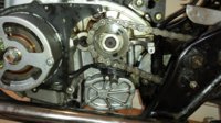
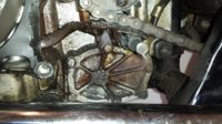
For what its worth, when I took everything out the first time the order was spring->cap->brass disc->plunger->snap ring->rubber top hat boot. There was no washer at all. Am I dealing with an earlier model m/c or something? The snap ring that was originally inside broke when I took it out so I foolishly tossed it - wish I still had it to measure. Any ideas? I think the next step are some of those cheap harbor freight hobby pliers, but I'm still nervous that the snap ring isn't going to fit; and then there's the issue of what to do with the washer - just let it sit between the snap ring and the groove where the top hat boot seats?


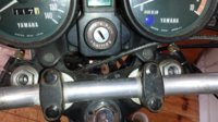
*Edit* as I mentioned before, my M/C has "ASCO 12" stamped on the bottom of the body and a 14 stamped on the top. I thought it a little odd that a reservoir o-ring I bought off Ebay was too thick, but figured the seller had the wrong part. In searching for ASCO12 master cylinder I'm getting results for RD400s and small Suziki GTs - kits available that look exactly what came out of my M/C (http://www.discountbikespares.co.uk...IT-ASCOAISHIN-GT550500380-GT250185125-GS.html) & (http://yambits.co.uk/fs1dx-brake-master-cylinder-repair-kit-front-p-33098.html). I'm officially confused - but I'm starting to think I have an RD400 Master Cylinder. When I search RD400 M/C I get a lot of my m/c - doesn't seem to cross reference the xs650.
 
Last edited:
This link shows the XS360 ansd XS400, SR500 and XS650 all have the same componants as the #08-0219, (535-W0041-60-00), part Mikes is selling and should be the one you got.

Parts file shows the 535-W0041-60-00 part no for the D,E,F
 

Attachments

  • SE Front brake01.jpg
    SE Front brake01.jpg
    256.2 KB · Views: 141
  • SE Front brake02.jpg
    SE Front brake02.jpg
    259.9 KB · Views: 135
Well I'm done with the m/c rebuild for now - defeated for the moment.

I made my own m/c snap ring pliers with some long nosed pliers from HF and a dremmel, which actually came out pretty good; got a full compression of the snap ring and allowed me to get down into the bore fine.

However, ended up being a futile attempt. The bore that the snap ring can fit down measured 17mm in diameter. The snap ring (As mentioned prior) was 18.5mm decompressed. Compressed it measured exactly 17mm; so unless I could get the eyelets to not only touch but overlap, that thing wasn't going to fit. I got a bit aggressive with it and tried squeezing it in from the outside with some pliers and of course bent the snap ring, so that thing is toast; but I don't think it had any chance of ever fitting where it had to go.

I'm at about 3 hours and two knuckles in trying to get this m/c back together. I'm going to try buying my own washer and snap ring tomorrow one size smaller from the hardware store and see if I can have any luck with that.

Holy smokes can this get annoying. Beer time.
 
Weekend update. Actually got my old brake together but I bought that 11mm tw200 master anyway so I put that on today and my brakes should now be set. About to head out to the hardware store to buy a 27mm socket so I can change the oil and finally ride the bike for the first time.

One thing I noticed is that the forks are a bit rough, the po had electrical taped the dust boots and they are a bit stiff. I was going to check the fork oil but noticed the fork caps are seated at different lengths, im guessing this might be diffrtent preload? The flat screw insert on the left side is about a half inch deeper recessed into the forks, and I cant imagine these should be assemtryical. Thoughts?

Posted via Mobile
 

Attachments

  • 20140517_144154.jpg
    20140517_144154.jpg
    185.7 KB · Views: 166
On those big sockets, I have them but have been looking at the prices in several stores. Lowes, Tractor Supply Company, Advanced Auto. Most places sell them for less than $10.
On the forks, yes, those are preload adjusters. They have three positions. Most consider setting them even is best. I think that's fine but you can set them different. Lets say the middle position seems a bit soft, the bottom position a bit stiff. Then set one at the middle, one on the lower.
This may sound like not such a good idea but on some bikes they use one fork a damper type and the other a cartridge type.
If you think this difference in tension will push one fork down faster than the other, it can't. The front axle clamping the forks together and the strong bracing of the fender prevent any shifting of that sort.
When you go to remove the fork caps loosen upper tree clamp bolts. with these tight they not only clamp the tube in the tree but clamp the cap in the tube.
It's hard to catch the oil when you drain it. You usually need to pump the forks up and down to get it all.
Once it's all out I put about 8 ounces of what ever cleaner you like into the forks. I use kerosene. pump the fork up and down a few times, drain it out, repeat till it comes out clean.
I then put in about 8 ounces of oil, pump, drain, this gets the last of the kero out. Or you can let them drain out over night.
Now comes the important part, refilling with the proper amount of oil. The book lists several different amounts and types of oil for the forks. These are mostly not enough oil. What ever oil you choose, ATF, 10, 15, or 20 w fork oil. Put in 8 ounces. Pump up/down to remove any trapped air.
With the forks fully collapsed you need to set the oil level 6 inches down from the top of the tube. I use a piece of clear tubing. Measure 6 inches from one end. Mark the tubing, I use a zip tie. Now inset this 6 inch end down into the fork till the zip tie sets on the top of the fork tube. Suck on the clear hose, I use a Mity Vac tool, using your mouth works. This draws out the oil above 6 inches down.
This works out to an ounce or two over what the book calls for. This creates a smaller air space above the oil in the fork. This increases the air pressure in the fork when you use the brakes. This creates a stronger air cushion that helps decrease the brake dive.
There are many mods you can do to improve your fork action. Trying several weights of oil is easy and won't cost much. Replacing the Springs is another. I did the Minton Mods to mine with new straight rate springs and they work a lot better than stock.
Cartridge emulators are another mods that a lot of people like.
Just remember, with all this improvement of the front suspension the rear should gets some too. The stock shocks weren't all that great when new. Good replacements can run into some money. 650central has Progressive shocks, Semi custom made. Call him, talk about your bike, riding style and weight. He will assemble a set of shocks with the right springs to match your specs.
Leo
 
Fantastic response, thanks Leo. Im going to put the forks on hold for now, knowing that they at least function.

So oil change done, everythinf back together and..no maiden voyage. When I first stuck the battery in it idled smoothly at 1k, im afraid between warming it up a few times over the past few weeks without riding it has sapped my battery, so ill throw it on a tender and try again tonight. I can get the bike to start but now I need to hold the throttle at 3k or itll sputter out, and its taking quite a few kicks to start.

Cosmetically I think im satisfied for now, just need to get it on the road to actually ride now.

Posted via Mobile
 

Attachments

  • 20140518_130226.jpg
    20140518_130226.jpg
    304.1 KB · Views: 179
Back
Top