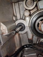
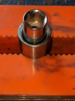
Agreed, all good points Skull.

I guess if you guys think this is worth pursuing with Mikes a thread could be started in that forum.

I haven't been here long enough to know if there have been any actual failures or installation problems. And haven't tested this one yet.

Maybe as per your earlier suggestion someone here has some relationship with cruizinimage and could approach him?
 
They obviously aren't prepared to go through the effort and expense of retooling, new molds, loss of existing inventory, etc.
Haven't replied yet. Not quite sure what to say. Not at a loss for words, just taking some time before I decide which ones I want to use.

Maybe they haven't had any cases where the part was not able to be installed because they just never heard about them?

This part looks unacceptable to me. Jim seems to concur. Am I wrong?
Robin,

You and Jim documented what seems to be a substantial concern with this product.

In my opinion, it is always a worthwhile effort to give a company feedback about a product anomaly. Otherwise, they can get lulled into focusing only on sales and profits.

You recieved what appears to be a defensive, knee-jerk reply. Perhaps there is some deeper consideration happening, as well.

When I complained to Mikes about the rapid deterioration of their nylon fuel products (upon exposure to ethanol fuels), I got a quick acknowledgement of the existence of the problems. This is unusual, in my experience, as companies are very hesitant to admit to mistakes in fear of exposure to any sort of claims by those who might have suffered from product failures.

Lets hope that some activity has resulted from your substantial letter.
.
 
companies are very hesitant to admit to mistakes in fear of exposure to any sort of claims by those who might have suffered from product failures.
Agreed.

Perhaps there is some deeper consideration happening, as well.
Lets hope that some activity has resulted from your substantial letter.
.

Let's hope so Dude, although I'm not holding my breath, and thank you for your response at this hour.
6000 parts at $39.95 apiece = $239,700 USD I expect that has more than paid for these at Foreign Market manufacturing costs, although that is just unsubstantiated speculation.

Once again I am just speculating here, but perhaps this is a new part run by a different supplier as 5twins has revealed?
By chance I and then Jim happened to pick up on this. Maybe the earlier parts by a different supplier better met specs?
It would appear so from gggGary's earlier post.

I am disadvantaged by being a new guy here and new to this game and am simply reporting what I find for the Guru's to comment on so that no-one ends up doing any harm to their engine.
If I'm wrong, OK, I'm willing to admit that because of my inexperience. If I'm right, what the heck do we do?

Hope for a new supply of OEM parts I guess.

Although gggGary has said that these are very likely usuable, perhaps with a little attention and his is a voice we can trust.
 
Last edited:
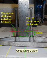
Pics thanks to gggGary

Not to scale. Measurement is true from when i was working on it. Cannot be used as a datem
camguide5 copy.jpg a.jpg camguide4 copy.jpg
 
...Maybe the earlier parts by a different supplier better met specs?
It would appear so from gggGary's earlier post...

I also got my (2) MikesXS front guides in 2013. In doing the comparison album, I drilled precisely spaced and close-fitting holes in the base fixture, to ensure that the guides were precisely aligned for the comparison. If the M6x1.0 mount screws were angled, they wouldn't have been able to be fitted, and I would've reported as such...

http://www.xs650.com/media/albums/front-guide-slipper.1640/
 
Pics thanks to gggGary

Not to scale. Measurement is true from when i was working on it. Cannot be used as a datem
View attachment 115990 View attachment 115991
Good stuff Skull! I should attempt to mount that guide in a cylinder...
Wonder how many guides are in their casting molds? Sand cast, investment cast? Wouldn't take much to corbel away a bit of the mold or add to the core to widen the "bolt bulges"
Than a half way decent fixture to drill holes...........
Still thinking that cruisinimage might be able to find work with the OEM maker if Yamaha has truely discontinued the part. Cruisin supposedly uses the OEM piston manufacturer, might even be the same company.
 
Last edited:
Thanks for that confirmation 2M.

I think the least I can do in my response to them is to let them know that this bolt hole angle issue applies to parts shipped this year and that parts shipped in 2013 were much better. Maybe they can inform their manufacturer to correct the angle when drilling these holes in the future.

Ok if I attach one of your pics to my reply gggGary?
 
Hey guys looking for a little direction and advice based on your experience. Looks like things might start to warm up a bit around here soon…….maybe…... so I want to get back to this engine reassembly. Before I do that though I thought I’d replace some seals while it’s on the bench.

My questions, at this point, have to with the tach drive seal. I know removing seal #3 with the cover on the bike can be done with a small bent dental pick if you’re careful to not pull up on the tach drive shaft and drop the washer in the case.

I know you all know this pic but inserted here in case it needs to be referenced.

tach gear.jpg


But I’m wondering how important it is to replace the o-ring #2 as well. And to do so can this be done while the cover is in place? I have both OEM seal and o-ring.

Should I just pull the cover off so I can do both and not worry about dropping the washer?

I’m just trying to save damaging the new gasket that I installed after starter gear and clutch work was done just prior to pulling the engine.
It was installed with Hylomar Blue so I guess it should come off fairly easily.

Also I’m not overly concerned about inspecting my oil pump as it was functioning fine. Unless there is something I should look at.

What is the best way for me to tackle this? Cover on, cover off?

wax 4.jpg


Thanks guys.

BTW: front cam chain guide update

Today I spent an hour or so visiting and chatting with Terry Wolfe at Wolfeworx.
He is the mechanic/machinist who did my engine rebore work and is an OEM Yamaha (and other) parts supplier.
His parts guy wasn't in so Terry asked what I was after. Told him Sage was getting a name for me at Yamaha Canada and why.
Terry picked up the phone and called his buddy who is the top guy at Yamaha Canada. Our guide is NLA and no more will be produced.

There are 2 left in the world in the Yamaha dealer parts network, both in Australia.
So no point worrying about sending any letters.

And apparently MikesXS has no intentions to do anything about their part. I did reply to their original email mentioning 5twins idea that the solution was really pretty simple. All they would have to do is get their supplier/manufacturer to correct the angle when they drill the holes on future parts.
They are not going to take any action.
 
..... and we're not going to buy those P.O.S. things anymore, simple as that, lol.

To determine whether or not the o-ring needs replacing, you'll need to look at it. If it's all flattened out then yes, replace it. If it's still round and "o-ring" looking, it should be fine. Was it leaking? That would be the other reason for replacement but it's difficult to tell, if you have a leak in that area, whether it's the o-ring or the seal.

You can pull the sleeve out with the cover on if you're careful and hold the tach drive rod down in place as you lift the sleeve out. There's a little hole in the top end of the rod (for the drive cable) so you should be able to hold it in with something pointy like a small awl.
 
Thanks 5twins. Yes it was leaking but as you mentioned I couldn't know if it was just one or both. I'll carefully pull it apart as per your suggestion and have a look at the o-ring condition.

Terry asked me to bring him an old guide and the new one with some cylinders (I have a pair of jugs in buddy's spare engine in a box) and he's going to look into what he might be able to do and whether there might be enough meat there for a time-sert.

Thanks again for your advice.
 
Last edited:
Seals, seals and more seals.

Finally made some progress yesterday and today.

Back on Nov.15, 2017 Jim said this......
If it were me, I'd replace every seal in it while you got it out. They're 40 yrs old... how much longer do you want to run em...:)

Of course, I said this……..
Ah Dadgummit Jim.............ya.

Started with the easy ones, the camshaft seals. Pushed them out with a 26mm socket.

IMG_20180501_110705.jpg


Then pushed the new ones in using 5twins plywood in a vice trick…….very easy, great tip 5twins..

IMG_20180504_160252 (1).jpg


Onto the clutch push rod seal and bearing. In spite of being somewhat reluctant to take a drill bit to my engine case everything went according to Hoyle.

IMG_20180503_141817.jpg


Used the shorter outer pushrod as a guide with a 8mm socket to seat the new XS650Direct bushing.

IMG_20180503_150454.jpg


When researching this I came across a post by 2M linking to another about using a Dremel with a ball stone to chamfer the case for the new bushing. Worked great. Lost a wee wisker of seal when installing, and one tap too many on the socket/seal driver, but I think I’ll be OK. If not and it does leak, easy enough to replace with the spare in one of the parts boxes.

IMG_20180503_152907.jpg


NOS long push rod installed.

IMG_20180503_145722.jpg IMG_20180503_154302.jpg

Next up, countershaft seal.

IMG_20180503_154746.jpg


Rooted around in the plumbing box and rigged up a seal driver from some 1 ½” ABS parts.
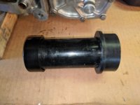
IMG_20180503_162857.jpg

Now to the crank seal.
One of the stator screws broke free by hand, needed the hand impact for the other one.
After stator removal, an electric impact had the nut off, and the rotor pulled slick as can be.
Bob, I read through your 60th birthday present thread on you doing this job and used your tip to prevent nicking the case.

IMG_20180503_171623.jpg


This seal did not want to give it up. Took a lot more effort than the other two.
I thought I could finish it off without my block and got a nick…...ah well, cleaned it up with a small file.

IMG_20180503_173506.jpg


Did some more rooting around in the plumbing box and rigged up another seal driver.

IMG_20180504_140038.jpg

Last one, tach drive seal and o-ring. 5twins suggestion to hold the tach drive shaft in place with an awl worked great. This pulled out with no effort whatsoever which when looking at the condition of the o-ring is understandable.

IMG_20180504_141055.jpg


Boy that tach drive seal was a tough little beggar as well. Bent up a little dedicated tach drive seal puller. Tried to push it out but prying was easier.

IMG_20180504_144433.jpg

Used a ¼” 8mm socket seal driver.

IMG_20180504_151029.jpg

So, new seal and o-ring. Interesting that the new OEM o-ring doesn’t appear to fill the gap a whole lot better than the original but it did 'pop’ and seat nicely into place on install.

IMG_20180504_151422.jpg


Hopefully I’m leakproof now.

IMG_20180503_215250.jpg


Joe.jpg


Tested the rotor slip rings.

Slip rings 6.0 ohms
Leads 0.6 ohms

Result 5.4 ohms

So it looks like my rotor is good which makes sense as my Voltmeter always showed things were working fine.
Ran out of time today so I will pull the brushes and measure/replace if necessary tomorrow.

Of course I have a few questions.

Haven’t really been able to find an answer I like to this one regarding the countershaft sprocket nut. I have seen the chain trick in the Haynes manual, pg.60……and don’t know that I like the looks of that.
Could maybe do something like this with a socket on the bottom teeth? Old sprocket shown for illustrative purposes, new sprocket will be installed. Although I'm not sure that looks much better than the chain method.

IMG_20180504_194033.jpg


1. Is there any good way to tighten that nut up to 90 ft. lbs. with the engine on the bench or should I wait until it’s back in the bike, new chain installed and use the rear brake? How do you guys do this?

2. Same question regarding the rotor nut. I could get buddy to hold the rotor wearing a pair of gloves.This appears to be another one that Yamaha changed the torque setting on over the years. I have read anywhere from 25.5 to 58 ft. lbs.
What is the accepted torque setting on this, should I wait until it's back in the bike and use the brake again, do you guys have a trick on how to do this?

3. Also thinking ahead as I’m getting real close to reassembly I do have another question.
I know I can do the static timing on the bench with an ohmmeter but was wondering If I could jumper my battery to the points wires bullet connectors and use a bulb? Any reason not to do this?

And one more question.
4. Before I start reassembly thought I'd better check with you guys on this. I have read that it is seldom necessary to replace the rear cam chain guide/tensioner as the rubber is much more robust.

4. Does this one look ok, or should I get a Mike's/XS650Direct replacement as much as that pains me?

IMG_20180420_153400.jpg


Sorry for all the questions guys, but I'm not sure about these things and want to get it right.
Thanks again for all your help.

Oh, and before doing these seals I spun it around 180° and polished up the right side case a bit.
It’s a lot easier on the bench rather than in the bike. DAMHIKT

IMG_20180501_215120.jpg


IMG_20180501_214335.jpg
 
Great write up Robin, really nice work on those seals, it’s a little nerve wracking driving that seal puller into those old seals isn’t it? You’re afraid of scratching something up.

As far as tightening up your drive sprocket and rotor, I’m sure you could do it on your bench, but it might be a little more difficult just because you’re going to have to try and hold your motor stable while you’re also juggling wrenches and holding the rotor and sprocket from moving, If your stand is really stable you might get away with it.
The rotor , I’m trying to remember, I think I was just able to hold it with my hand. The sprocket, I jammed a block of wood in there to hold it.

Your polishing work is some of the nicest I’ve seen, well done! I’m following with great interest!
 
Wow, sidecover looks great!

1. I'm a member of the meatball surgery zipgun crowd. With my 250 ft-lb rated 1/2" pneumatic, trans left in neutral, I'll hit the sprocket nut with just a short shot, let it spin down, and hit it again. Just short shots, don't overspin. The reactive torque of the countershaft is enuff to get the nut torqued down. Unfortunately, this is a time-learned thing, knowing how much zipgun equals torquewrench value. Your call.

2. I like the lighter 25 ft-lbs. It's a keyed taper fitting, doesn't take much to hold, and the usual rule-of-thumb of "just past lockwasher crush" works for me. Again, done with zipgun.

3. If you jumper the battery +12v to the points, you'll get a dead short as soon as the points close. Jumper battery to lamp, other side of lamp to the points.

4. That tensioner looks worn to me. I'd replace it.

Great job so far...
 
Thanks Bob. Buddy can hold the engine steady while I tighten things up. Was wondering how to stop things spinning as well.
Maybe the guys will have some suggestions. I can have him hold the rotor and got lots of blocks of wood to hold the sprocket if that will work up to 90 ft. lbs..

Curious though as to what the proper torque setting is for the rotor nut. Quite a range I've found.
 
Thanks 2M, the cleaning and polishing is the easy stuff for me, it's the rest of this that's new territory.

Thank you for suffering through answering all my questions. I also have a pneumatic zip gun and will proceed as you suggest. Can check again once it's back in place I guess.

Good confirmation on how to set up a test lamp. Figured it would be nice to be able to use a lamp as well as an ohmmeter.

Guess I'd better hit the Check Out button for everything in my shopping cart.

Once again, thank you for all your advice.
 
Rob, if you're uncomfortably with the zipgun approach, then your idea of blocking the sprocket can work. But, don't doit with the socket set thataway, the leverage angles in that position will produce forces exceeding tons.

Maybe you could cook-up an anti-torque holder, like the red lines in this pic.
Robinc-Sprocket02.jpg

The torque arm would be around 2" (green line), making the 90 ft-lbs into a 540 lb compression on the holder. Have a broad/curved foot that abuts the case bulge, to distribute the force. Maybe a carved piece of wood (your speciality), with an inserted steel pin to fit into the sprocket's tooth gap. A 1" x 1/2" piece of hardwood should easily handle 540 lbs. Design it right, and you may be able to flip it over, set atop the sprocket, pressed against the bulge, to loosen/remove the sprocket nut...
 
Back
Top