Yamaha p/n 4X7-12159-00-00 used in "large" Viragos from 1981 750 thru 1999 1100, in VStar 1100 from 2000 thru 2009 and in VStar 950 from 2009-2014. They are slightly shorter than stock 650 adjusters and adjust using a hex key.
-
Enjoy XS650.com? Consider making a donation to help support the site.
XS650.com receives a small share of sales from some links on this page, but direct donations have a much greater impact on keeping this site going.
You are using an out of date browser. It may not display this or other websites correctly.
You should upgrade or use an alternative browser.
You should upgrade or use an alternative browser.
XS650 Valve and Clutch Adjusters, Resurfacing
- Thread starter TwoManyXS1Bs
- Start date
-
- Tags
- engine maintenance
Yamaha p/n 4X7-12159-00-00 ...
Thanx, Aldo5468. That adjuster appears in a long list of Stars and Yamahas.
http://www.yamahapartsnation.com/oemparts/p/yamaha/4x7-12159-00-00/screw-valve-adjusting
It's also offered by MikesXS, and includes the locking nut.
https://www.mikesxs.net/parts/yamaha-xs650-tappet-adjuster-screw-and-nut-oem-4x7-12159-00
I'd be curious to know what its tip radius is...
Well the good news is; I have plenty of XS motors........

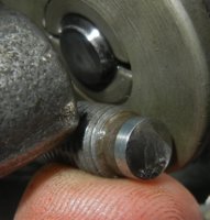
Put in a good hard day today,about 240 miles 50 or 60 at 9/10's, fast as I could go chasing sport bikes. At the end of the day I could hear the valves a bit, so checked them. Here's the pics;
A couple of the adjuster ends.
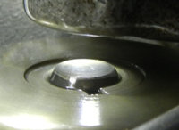
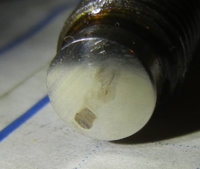
This valve had gone from .006" to .009" Doesn't look like .003 of wear, could have been an error on my part or a bit of carbon? The others were the same as set to about .001 wider.
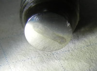
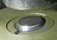
valve stem ends all looked good, still working on getting the photo lighting right.
got 145 psi L & 149 R and the plugs look good.
78 79 BS 38s UNI foam in the stock airboxes, commando mufflers, pamco, mech advance, an accel coil. I would call this the best running XS motor I have owned. Coming straight from a hard flog to to a stop for others to catch up it would sit and idle without a burble then go right back to it for more.
Kind of interesting the tracks look a little longer than those on the stock grind but far from the edges yet. I think there are 3 with the "silver ends" the other exhaust had a regular adjuster.
She's back together and ready for more.

Put in a good hard day today,about 240 miles 50 or 60 at 9/10's, fast as I could go chasing sport bikes. At the end of the day I could hear the valves a bit, so checked them. Here's the pics;
A couple of the adjuster ends.


This valve had gone from .006" to .009" Doesn't look like .003 of wear, could have been an error on my part or a bit of carbon? The others were the same as set to about .001 wider.


valve stem ends all looked good, still working on getting the photo lighting right.
got 145 psi L & 149 R and the plugs look good.

78 79 BS 38s UNI foam in the stock airboxes, commando mufflers, pamco, mech advance, an accel coil. I would call this the best running XS motor I have owned. Coming straight from a hard flog to to a stop for others to catch up
 it would sit and idle without a burble then go right back to it for more.
 Kind of interesting the tracks look a little longer than those on the stock grind but far from the edges yet. I think there are 3 with the "silver ends" the other exhaust had a regular adjuster.
She's back together and ready for more.

Great pics, gggGary. Quite revealing.
A bit of a mystery there. 0.003" is a lot. I can understand 0.001", from wearing-in. Maybe the valve tip is a bit uneven, and the valve rotated to a larger clearance.
Yes, the longer/wider track reveals the larger 19mm tip radius, hopefully to spread the loads. There may be some micro roughness on the valve stem tips that transferred to the adjusters. Notice how the wear track on the first adjuster is more pronounced in the first 30% of its contact. This shows that the most severe loads on the valvetrain parts occurs in the first 30% of valve opening travel, when its accelerating the valve, and fighting the valvesprings.
Scratching your fingernail over these wear tracks, can you detect them at all?
Looking at the pics of your original adjusters, reverse engineering the track marks, I'd guesstimate that they were originally ground with a 14mm (9/16") radius.
...This valve had gone from .006" to .009" Doesn't look like .003 of wear, could have been an error on my part or a bit of carbon? The others were the same as set to about .001 wider.
A bit of a mystery there. 0.003" is a lot. I can understand 0.001", from wearing-in. Maybe the valve tip is a bit uneven, and the valve rotated to a larger clearance.
... Kind of interesting the tracks look a little longer than those on the stock grind but far from the edges yet. I think there are 3 with the "silver ends" the other exhaust had a regular adjuster...
Yes, the longer/wider track reveals the larger 19mm tip radius, hopefully to spread the loads. There may be some micro roughness on the valve stem tips that transferred to the adjusters. Notice how the wear track on the first adjuster is more pronounced in the first 30% of its contact. This shows that the most severe loads on the valvetrain parts occurs in the first 30% of valve opening travel, when its accelerating the valve, and fighting the valvesprings.
Scratching your fingernail over these wear tracks, can you detect them at all?
Looking at the pics of your original adjusters, reverse engineering the track marks, I'd guesstimate that they were originally ground with a 14mm (9/16") radius.
Last edited:
Closer look at your 5th pic, some things got my attention.

A- Wear track on the valve stem end makes me wonder if the valve fails to rotate.
B- Dual wear tracks on the adjuster, as though it was readjusted about 0.004" during use.
About 9° of adjuster rotation will change clearance 0.001" (0.025mm).
C- What's this gritty stuff?
A- Wear track on the valve stem end makes me wonder if the valve fails to rotate.
B- Dual wear tracks on the adjuster, as though it was readjusted about 0.004" during use.
About 9° of adjuster rotation will change clearance 0.001" (0.025mm).
C- What's this gritty stuff?
I may revisit that valve, bike's still on the lift.
I think the "grit" may be paper towel fluff. there is a slight "dig" at one end of the track.
I also noted the "super stock" 79 valves are a bit loud, it's at 10,500 now about 800 since it's wake up last summer. may do a look see in there.
I think the "grit" may be paper towel fluff. there is a slight "dig" at one end of the track.
I also noted the "super stock" 79 valves are a bit loud, it's at 10,500 now about 800 since it's wake up last summer. may do a look see in there.
angus67
Welder's penetrate deeper!!
Lack of rotation of valve could be a slight bend, near undetectable in valve stem catching in guide. Perhaps your "italian tuneup" moved some carbon around on the valve seat/ stem.
Your plugs look a bit cold. Shouldnt the ground strap be clean about halway between the tip and threads?
Your plugs look a bit cold. Shouldnt the ground strap be clean about halway between the tip and threads?
Your plugs look a bit cold. Shouldnt the ground strap be clean about halway between the tip and threads?
I checked the plugs partly because this motor is using a little bit of oil. I asked the guy behind me and he said never a hint of smoke. 35 year old valve seals.... perhaps the intakes are weeping a bit. That shot was lit with a blueish LED headlight color is more brownish than it looks. I need to do the tach drive seal, but doubt that is a noticeable oil user.
Yeah she got a full on Italian tuneup yesterday. Was trying to stay up with guys on liter bikes and they were running 80-90 on the straights. I think I pushed one guy too hard, must have been bugging him to look in the mirrors and see an XS650 on his taillight. :smirk: He went off a couple of corners. I backed off, moved back in the pack after break. The traffic picked up and slowed us down anyways. I am a bit too susceptible to race-itis. bbbBad gggGary.
Cool thread... great info and something that I'm likely to be more observant as I go to adjust my bike.
Unfortunately, I know nothing about metals and their principals so pardon my ignorance, but how does one go about hardening the tips? Is that a heat up and drop in water kind of thing?
Also, on the regrind of the clutch pushrods, does doing so decrease the adjust-ability of the clutch, since you're removing material?...or is it so minor that it's a non-issue...would "hardening" those also be needed?
Thanks for the insight!
... how does one go about hardening the tips? Is that a heat up and drop in water kind of thing?
Kinda. "Heat treating" steels is both a science and black art. Simple if done correctly, disasterous if not. The world of "Steel Alloys", "Metalurgy", "Case Hardening", "Tempering", is both fascinating, and a deep black hole. If you research these, we may not see you for awhile. There's formulas for various steel alloys, and the real challenge is figuring out what mystery steel you're working with. During the grinding process, I can 'read' the shower of sparks, and make a guess as to the amount of carbon. I don't have a hardness tester, so I just do a file scratch test. If I get a scratch, then I'll heat the adjuster tip to bright red, with a case hardening powder, hold it there awhile, and quench in water. Then, polish a surface, gently reheat until I get a 'straw' color on that polished surface (tempering), and let it slowly cool. Not an industrial process, more of a shop quickie. Not necessary on valve stem tips, since they have a layer of stellite. Best to learn this first on chisels and old knife blades.
... Also, on the regrind of the clutch pushrods, does doing so decrease the adjust-ability of the clutch, since you're removing material?...or is it so minor that it's a non-issue...would "hardening" those also be needed?
There's sufficient adjustability in the worm adjuster to take up *some* slack from a regrind. I've found the clutch pushrods to start at 243mm length. More than a couple millimeters shorter could be a problem. The original design has a 5/16" ball pressing against a flat tip, and with a typical force of about 400lbs to disengage the clutch, that force over such a tiny contact area can be beyond 100,000psi, beyond the yield strength of normal steels. The 'dimpling' trick published by XSJohn (rip), helps alleviate this tremendous single-point pressure, plus keeps the pushrod centered. So, you're left with the 'wear factor' of spinning balls in dimpled ends, since this is the equivalent of a clutch throwout bearing. A bearing industry report showed max life expectancy occurs when the balls are 1 RC harder than the races. If you're using RC 60 balls, then a tip hardness of 59 RC is best, and that would call for hardening of the tips. Overkill? Probably. Just blathering here...
Good Stuff!
Thanks!!!
Thanks!!!
angus67
Welder's penetrate deeper!!
You lost me at black hole.
When i need a harder edge, i heat it red hot, throw it in used motor oil. Spark test shows small orange sparks after, indicating more carbon than before. I was unaware of this scratch test, but it makes sense
When i need a harder edge, i heat it red hot, throw it in used motor oil. Spark test shows small orange sparks after, indicating more carbon than before. I was unaware of this scratch test, but it makes sense
I found that quenching rebent leaf springs is not a good idea! I also found out that quenching a bar of red hot steel in a glass jar full of oil in the basement can get a bit exciting! took the the top off that jar right at the oil line as neat and clean as a fine diamond saw!
Some pics of the Left exhaust the one that went large on clearance.
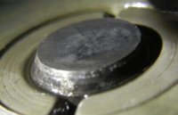
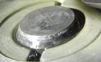
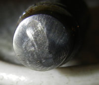
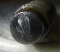
I am up against the limits of my point and shoot, using a Nikon S8100 in highest rez in close up mode lens about 3" away, lit by an LED ball cap light, then cropping. On the valve stems, that I have to shoot at an angle, you can see the depth of field is getting down to about 1/8"!
Put another 100 miles on it last night after the pics, sounds good.
Some pics of the Left exhaust the one that went large on clearance.


I am up against the limits of my point and shoot, using a Nikon S8100 in highest rez in close up mode lens about 3" away, lit by an LED ball cap light, then cropping. On the valve stems, that I have to shoot at an angle, you can see the depth of field is getting down to about 1/8"!
Put another 100 miles on it last night after the pics, sounds good.
At this blow up you can clearly see the track across the tappet end with a detent at both ends. This kinda jives with how the the feeler gauge works, the minimum valve stem/tappet distance is at the back or "cam side".
Thinking on this Ima gonna guess the first dent is the cam profile driving the tappet into the valve stem, the second is valve lift off/return as the cam goes "over the hump".
These tappets got about 250 miles on them, about 50 of that at "full tilt" with a lot up and down the gears shifting, at lets say 6K+ (no time to be looking at the tach). The straights were run at 80-90 MPH stock gearing.
I keep meaning to make a mount for a "wiggle gauge" to measure valve clearance directly.
...Some pics of the Left exhaust the one that went large on clearance.
I am up against the limits of my point and shoot, using a Nikon S8100 in highest rez in close up mode lens about 3" away, lit by an LED ball cap light, then cropping. On the valve stems, that I have to shoot at an angle, you can see the depth of field is getting down to about 1/8"!
Put another 100 miles on it last night after the pics, sounds good.
Still, those are great pics.
I'm not seeing the typical small diameter 'torroid groove' depression in your valve stem tip,
Like this:
View attachment 31557
That is from this thread: http://www.xs650.com/forum/showthread.php?t=28536
So, I'm thinking that this new tip radius is initially contacting the valve stem tip in a new/unused area, outside of any previous 'torroid groove' depression, and things are simply wearing in. Might've been a different story if the valve stem tips had been resurfaced.
Agreed and those valves "had" the start of that depression. A pic before the new tappets were installed; as Yamaha built it with about 8K miles and one known valve adjustment.
View attachment 63939
The new tappet grind evened it out????
Would like to hear what Jack and Gary Hoos would say on this?
View attachment 63939
The new tappet grind evened it out????
Would like to hear what Jack and Gary Hoos would say on this?
At this blow up you can clearly see the track across the tappet end with a detent at both ends. This kinda jives with how the the feeler gauge works, the minimum valve stem/tappet distance is at the back or "cam side".
Thinking on this Ima gonna guess the first dent is the cam profile driving the tappet into the valve stem, the second is valve lift off/return as the cam goes "over the hump"...
Yes, the acceleration profile of camshafts on valve parts is intense.
In this graph of high-rpm valve motion dynamics:
The red line is: Valve position, or travel
The green line is: Valve velocity
The blue line is: Valve acceleration
So, at high-rpm, the greatest forces on the adjuster tips occur in the initial and final stages of valve lift.
At low-rpm, the greatest forces are found at the peak of valve lift, due to fighting the valve springs.
This puts the greatest loads at the endpoints of the adjuster tip's wear tracks.
... These tappets got about 250 miles on them, about 50 of that at "full tilt" with a lot up and down the gears shifting, at lets say 6K+ (no time to be looking at the tach). The straights were run at 80-90 MPH stock gearing.
At least things didn't blow up, and you put liter bikes on notice.

As rpms climb, that 'acceleration' curve skyrockets...
I keep meaning to make a mount for a "wiggle gauge" to measure valve clearance directly.
Now, THERE'S an idea!
Have you tried the adjuster gadget I threw in the box?
From here: http://www.xs650.com/forum/showthread.php?p=417274#post417274
...The new tappet grind evened it out????
That's whut I'm thinkin'.
... Would like to hear what Jack and Gary Hoos would say on this?
Absolutely! Chime in guys. And, don't cut any slack.
With all this solid tappet banter, this thread could easily morph into a sales promotion for "Elephants Foot" or "Kedo" adjusters.
Similar threads
- Replies
- 33
- Views
- 2K
