Yamaha XS650 Valve Train Geometry

Once again 2M - your work is remarkable: thorough, methodical and well-considered.

Let me know if you'd ever like to do a Masters in Mechanical Engineering... :lmao: ....or supervise me while I do another one.

Pete
 
A lil' update to this thread.

Member Paul Sutton raised some interesting questions regarding valve rotation.

http://www.xs650.com/threads/engine-valves-not-rotating.49609/

So, I wanted to explore the adjuster tip's scrubbing action in a little more detail. A new spreadsheet was written that shows the incremental scrub values for each degree of rocker rotation, from 0° (closed valve) to 12° (full open).

Here's the incremental scrub values for a stock 8mm adjuster tip radius:

Adjuster-Scrub08.jpg


The incremental scrub values are listed down the far right column. The adjuster tip will be doing most of its 'outward' scrub (pushing the valve stem outward) at the beginning of valve lift, reducing to zero scrub at about 3/4ths of its travel, then reversing the scrub slightly (pulling the valve stem back inboard) at the last 1/4th of its opening travel.

Here's the incremental scrub values for a modified 19mm adjuster tip radius:

Adjuster-Scrub19.jpg


Even though the tip has a larger 19mm radius, and the tip sweep across the top of the valve stem is greater, the total and incremental scrub values remain the same. I tried tip radius values from 6mm all the way up to 24mm, and the incremental scrub values, at each degree of rocker rotation, all remained the same! Quite interesting, and revealing.

I'm thinking that having the scrubbing occur closer to the valvestem centerline, more inline with the rocker/valve offset, may help to induce valve rotation. If so, then that calls for a smaller tip radius, like the original 8mm tip radius.

Counteracting this valve opening 'scrub' action is the mirror-image reverse 'scrub' that occurs during valve closure. The question now is: Which one wins, and what direction does the valve rotate? Does greater tip pressure during opening override tip pressure during closure, or the other way around? And, what are the valve springs trying to do during all this?
 
I need to open up that 79 motor and look at the valve action again with the stock adjusters reinstalled for about 3K miles now. I did a quick right exhaust reset before a trip last last week cause the noise was driving me nuts but need to do a more relaxed lookie see at all them. I was thinking there can be a variation of where the rocker aligns with the valve stem in production but the springs should do the turning?
 
Very cool, TwoManyXS1Bs.

Here is a little valvetrain project I'm working on myself for the SR/TT500 (they have similar valvetrains to the XS650).

I'm interested in observing how the lift curve changes from the lobe to the valve. I currently have two examples of aftermarket camshafts and a stock one being measured. I hope to get more down the road. The valvetrain has been accurately measured and mapped it out in CAD.

I'm also interested to see if the camshaft companies are using lobes designed for this valvetrain's geometry in mind, or if they're using lobes from another application "it's close enough". This will manifest itself in some weird things going on with the lift curves (and subsequently, velocity, acceleration, etc.).

Here is Camshaft 'A':

Measured lobe lift vs. Measured valve lift vs. Calculated valve lift (lobe lift * rocker ratio)-lash
Lobe_valve_rr_zpsmjsegzul.jpg

This would be the velocity and acceleleration curves. Notice how they change from the lobe to the valve.
LobeLift_accvel_zpshc10anec.jpg

ValveLift_accvel_zpsxkew0gid.jpg

And here is looking at the error between the measured valve lift curve and calculating it by (lobe lift * rocker ratio)-lash:
SSE_valvevsloberr_zpsl2iovdtk.jpg

Statistically, they correlate well, but you can see where the variation occurs.
ρ: correlation coefficient (-1 to +1)
MSE: Mean square error. You use this to look for bias. The closer to zero, the better.
RMSE: root-mean square error. Basically looking at deviation between an observed value and an estimator

Look at it this way:

The red line has a slope of 1:1. This would be the measured valve lift curve.

The black dots would be the lift point at each degree for the (lobe lift * rr) - lash. Since it sees each lift twice, it's either going to plot a value above, on the slope, or below. So either it's calculated to have a higher lift than the measured (above the line) or lower lift than measured (below the line). At around .200 valve lift they're essentially equal, but at lower lifts they're not and at higher lifts it trends down.

IMO, I think graphing it this way really demonstrates well the variation in the rocker arm geometry as it moves through its arc.
 
You guys are too much I just fix on em. Set the valves, exhausts and one intake a bit loose one intake was right at .003". pulled some adjusters to look at them and valve stems. Only got one pic that was decent, basically they all looked good, a light channel in the adjuster, stem ends looked pretty good, just a slight "rough spot"
Adjusters are original to the engine, 5K then 30 years in shed, a wake up, a few hundred miles with 2M's reground adjusters, then back to the factory pieces, now another 5K on it in the last 2 years.

DSCN7475.JPG


Start and run after valve and cam chain adjustment.

 
Last edited:
Fantastic graphs there, Hoffman900.

Your valve movement graph is particularly interesting in that it shows the zones of lash takeup and entry ramp. Whatever the valve lift is, at the end of the ramp, is the ideal lash value.

HoffmanEntryRamp01a.jpg


Your lift variance makes me wonder if the angularity of the rocker's arm wasn't accounted for. The effective arm length varies as the cosine of the arm's angle. In the case of the XS650 rocker, swinging thru -6° to +6°, the cosine factor goes from 0.995 to one to 0.995. Yeah, it gets complicated, google "vector mechanics".
 
"Your lift variance makes me wonder if the angularity of the rocker's arm wasn't accounted for. The effective arm length varies as the cosine of the arm's angle. In the case of the XS650 rocker, swinging thru -6° to +6°, the cosine factor goes from 0.995 to one to 0.995. Yeah, it gets complicated, google "vector mechanics"."

It was in the measured data.

What I was trying to highlight here is the fallacy of just multiplying the lobe lift by the rocker ratio (and subtracting lash) in getting the lift curve.

The idea of the exercise is to look at different camshaft offerings, including the stock, to see what the velocity and acceleration profiles look like. I'm a believer that not all the offerings were designed for this valvetrain geometry, and some of the camshaft outfits are using lobes from their lobe library that are 'close enough' but not ideal.

That particular 'Camshaft A' wasn't as a lobe designer pointed out to me the acceleration curves on the closing side (on the valve lift graph). He said a change in base circle could actually fix it to some degree.
 
Would be interesting to hear the methodology used to arrive at those beautiful graphs.
 
Would be interesting to hear the methodology used to arrive at those beautiful graphs.

The profile was measured on a CamDr type equipment and the valvetrain geometry was all accurately measured and drawn in AutoCAD.

Then I used Excel to perform analysis. To get 3 axis on the same graph, I just normalized the curves (hence no values a they would be worthless). I had to do some data smoothing of the acceleration curve and even then, it's still too rough to calculate Jerk and have anything that would look like anything.

I am reteaching myself MatLab, but I've let those skills atrophy for a decade, so I'm not quite back up to speed with it yet.Once I am, I'll do everything in that.
 
Coupla things in those camshaft 'A' cam and valve lift curves look odd to me. If the X-ordinate labels are crank degrees, then I'm seeing lift durations in the neighborhood of 340°-370°. And, why the big difference in overlap duration, about 90° cam versus 150° valve.
 
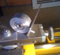
Back in Entry 20 TwoMany introduced us to a mystery machine which turned out to be a system for grinding lash screws to their correct radius. I must say I was very impressed with this lovely little device of his. During Spring I got to thinking as to how I could come up with something similar, not as professionally made, but more of an Ebay Far East knockoff. I came up with the following:

AGrind.jpg
I bored the aluminum bar so I could insert a bearing with an 8mm ID flush with the face. This was screwed to an aluminum based with a pin whose center lines up with the face of the bearing.
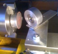
BGrind.jpg
The bearing assembly is located on a base attached to the lathe cross-slide using the pin. In the lathe chuck is another slice of aluminum bar with grinding paper glued to it.
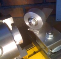
CGrind.jpg
Some PTFE plumbing tape is wrapped around the lash screw and a nut fitted. The distance from the back of the nut to the top of the lash screw's dome defines the radius. In my case I set this distance to 9mm. The lash screw is then placed in the bearing where it fits loosely rather than snug.
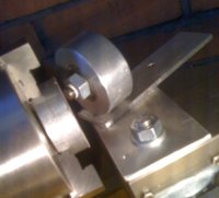
DGrind.jpg
The lash screw is then brought up to the grinding wheel where it can be rotated from side to side. The friction from the grinding process rotates the lash screw to give a nice smooth domed end. I used this to touch up my lash screws and also to convert a genuine VW screw from 12mm radius to 9mm radius. Testing with a radius gauge showed that I achieved a very good result.

In the next week or two I hope to receive a milling angle plate/vice for my lathe and plan to remake my grinder to a slightly higher standard, but I still will not match TwoMany's work of art.

Edit: I have rechecked the VW lash screw reground to 9mm radius after approximately 500 miles and all is well with no unusual wear showing.
 
Last edited:
Coupla things in those camshaft 'A' cam and valve lift curves look odd to me. If the X-ordinate labels are crank degrees, then I'm seeing lift durations in the neighborhood of 340°-370°. And, why the big difference in overlap duration, about 90° cam versus 150° valve.

The large duration is because it includes the lash ramps.

Here is the rocker ratio change with the roller rockers throughout the lift curve. This is why cam lobes for these OHC rocker engines are typically asymmetrical.

38208165405_846b1fe212_o.jpg


I'll have a stock Yamaha cam and an older Megacycle design measured up by later in the week.
 
Back
Top