-
Enjoy XS650.com? Consider making a donation to help support the site.
XS650.com receives a small share of sales from some links on this page, but direct donations have a much greater impact on keeping this site going.
You are using an out of date browser. It may not display this or other websites correctly.
You should upgrade or use an alternative browser.
You should upgrade or use an alternative browser.
2003 Royal Enfield 500 Deluxe
- Thread starter Raymond
- Start date
Thank you, @RC4MAN, forgive me being a bit fick, so looking at your diagram, you're saying I should find connectivity between the Earth and Main, Earth and Dip, but not between Main and Dip? So the one which has connectivity with both of it's pals is Earth?Lamps are not polarity sensitive, you can always use a meter to check for which wire does what
View attachment 254403
I can check that with an Ohmmeter before I wire it up.
You'll read resistance through all 3 because of the common earth. You're gonna need to measure. For example....Thank you, @RC4MAN, forgive me being a bit fick, so looking at your diagram, you're saying I should find connectivity between the Earth and Main, Earth and Dip, but not between Main and Dip? So the one which has connectivity with both of it's pals is Earth?
I can check that with an Ohmmeter before I wire it up.
Resistance across the main is 20Ω
Resistance across the dip is 40Ω
So, if you measure from dip to main, you'll read 60Ω... (series adds) because the path will be from the main, to the common earth, and across the earth to the dip.
So one combo will read total resistance across both elements. The odd man out will be the earth pin.
The two pins with the lowest resistance will (should) be the main. The odd man out will be the dip.
That make sense?

Uhm, yeaah, sort of, it's late now but I'll give it a try with the multimeter tomorrow. Hopefully will make more sense then . . .
This help?Uhm, yeaah, sort of, it's late now but I'll give it a try with the multimeter tomorrow. Hopefully will make more sense then . . .
Yes it does, thank you Jim.This help?
Last night - the wee small hours - got to thinking about a double filament bulb and this diagram looks muchabout what I thought. Your comments plus @RC4MAN made me realise both share a common earth. So measuring resistance across two spades, you're either measuring R1 or R2 or R2+R3. Highest resistance tells you the spade not being used is Earth.
It's a funny thing but light bulbs are something we're so familiar with, well, I've never thought about how they're wired inside. So previously I was thinking if I hooked it up wrong the bulb might blow. But I guess the possibilities aren't quite that dire - worst case you'll get both filaments on together.
LTGTR
XS650 Addict
Raymond - Seen something that reminded me of you today.
It has nothing to do with your current issue.
Went for a ride in the Adelaide hills and stopped for a coffee - a bloke pulls up on a W800 and we got chatting - It looks like it came directly from the showroom - i am not exagerating - he says its been a great bike and has only had to replace the stator since hes owned it from new - I asked him how many k's - 145,000 klms and it looks and goes like brand new - that sure says something for their quality.
Regards - Ray.
p.s. have you ever wondered why so many good looking people are named Raymond ?
Last edited:
Hi Ray, the W800 and its forerunner the W650 is one of those bikes that slipped under the radar with the biking public. Except in Japan and among customisers. Great traditional twin and built to highest Big K quality but the W650 was launched when people wanted faired-in plastic sports bikes. And now they all want Adventure bikes. Mine has done 37,000 miles from buying it new in 2014 with total reliability. I started a thread https://www.xs650.com/threads/kawasaki-w800.59441/post-687940 which is where you should have put this - no worries.
Well. Did the multimeter thang - set to 0-200 Ω and checked across A-B, B-C, A-C and it was all a bit inconclusive. Big word for a Friday. All the readings settled down to 0.6 or .07 which told me nuffin.
And then realised that all the diagrams, including @RC4MAN's and @Jim's, have A-earth, B-dipped, C-high beam. So I guess that's the answer then.
I'll just get me coat . . .
And then realised that all the diagrams, including @RC4MAN's and @Jim's, have A-earth, B-dipped, C-high beam. So I guess that's the answer then.
I'll just get me coat . . .
Checking them individually to chassis should easily indicate which is Earth, from that it's just a matter of hooking the other 2 up and swapping them if not correct.
I'm assuming your dilemma is that you have 3 individual wires rather than a 3 prong plug
I'm assuming your dilemma is that you have 3 individual wires rather than a 3 prong plug
Yes, that is exactly the problem - three spades and I pulled them all off. Was worried that if I connected them WWR the bulb would blow or something. But it looks like the l/h terminal, which I'm calling A, is generally earth/ground.I'm assuming your dilemma is that you have 3 individual wires rather than a 3 prong plug
boogerblaser
XS650 Member
No question is Stoopid. Unless you are Forest Gump maybe.Okey dokey, time for that stoopid question.
As work continues apace on rewiring the Bullet - heck, if I do one wire a day it'll only take a month - it now seems a bit rash that I pulled all three wires off the headlamp. Wish I had took a photo first 'coz I don't know what damage I might do if I wire them up wrong. If the Main and Dipped wires are WWR, well we're back to when the bike failed MoT test due to beam pattern - that was just a matter of borrow a screwdriver, swap two wires over, Bob's yer uncle.
But with all three off, will there be a risk of blowing the bulb if I hook 'em up wrong, esp the Earth wire? That might be Ground in N America?
View attachment 254400
So is there any way to tell by looking which terminal is which? Is there a convention?
Can't see anything on the bulb holder . . .
The mission is to save space and tidy up as the Bullet is rewired.
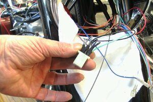
That there is a 6-way mini-connector. I'm using it for the common power and common earths in the casquette area. So that's side light, two pilots, speedo and ammeter lights, earths for those five bulbs plus headlamp and horn earths. Power to five bulbs and seven earth connections. 12 wires going into one little block. On the female side, you might see that the brown power supply from the LOSO switch is daisy-chained to two other positions and likewise one black earth daisy-chained to two other positions, one of which also picks up the horn earth, pale green.
To daisy chain, I cut some jumper wires, maybe 3", short bits of heat shrink as insulation, strip the ends, twist a couple together, lick of solder for good conduction, crimp to one mini blade.
On the male side, basically pairs of wires go to each blade. But I'll also put double-bullet connectors on the power and earths for the pilots so it can be took apart again.
The casquette - quint RE speak for headlamp shell - will have this 6-way connector block, a 4-way for power from iggy to all the switches, and two 2-ways for ammeter and turn signals. That's four connector blocks, a lot less than was in there before.
Hoping to shove all that in without ending up like that cupboard nobody dares open 'coz everything starts to fall out . . .
Some time this morning to continue the rewire.
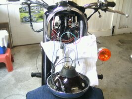
And I think that's about it for the front end, should be able to fit this inside ze casquette?
Meanwhile, this is what her back end looks like:
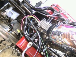
Better than the mess of about forty wires wrapped up in sticky tape. There's five wires on the right, four on the left and should pass along the frame neatly enough.
Onwards and upwards.

And I think that's about it for the front end, should be able to fit this inside ze casquette?
Meanwhile, this is what her back end looks like:

Better than the mess of about forty wires wrapped up in sticky tape. There's five wires on the right, four on the left and should pass along the frame neatly enough.
Onwards and upwards.
Scared of a bit of Scotch mist.
Wiring looking good. Wish I had the patience to rewire.
Wiring looking good. Wish I had the patience to rewire.
As work continues apace (yeah, right) to tidy the Bullet's wiring:
Your usual thoughtful work Raymond. Your bike will be better than when it left the factory!
Wiring looking good. Wish I had the patience to rewire.
Or the ability.
Or the ability.For me at least. I’m a hell of a cleaner upper, but to create a new harness? Not so much.
Yea same, but my ability doesn't match my patience,........and I don't have any patience...
Best thing I ever did was a full rewire on Taffy, with full Motogadget install. Learned a lot with the help from the lads hereYea same, but my ability doesn't match my patience,........and I don't have any patience...
 ……..
……..Funny it runs like sh
 t now……… is it me?….


If the Seinfeld TV show was still running, they could do an episode based upon your misery.Funny it runs like sht now……… is it me?….


