'78 SR500 street tracker

here's my 78 ... stock 10:1 Wisco with a home made copy of a Harley ERS 350 racing megaphone, I say it's a DL muffler (damn loud) spark plug pic is to blurred to see but looks good, running a NGK BP-8ES these are fun bikes:bike:
 

Attachments

  • S6300775.JPG
    S6300775.JPG
    283.4 KB · Views: 388
  • S6300777.JPG
    S6300777.JPG
    283 KB · Views: 309
Nice, dude!

Yeah, when I got it, I was afraid I would get bored with it quickly. It hasn't been the case. Certainly powerful enough for anything I need it to do. These bikes are way fun. I think the fact they are so narrow and light on their feet really makes it nice. They're a pleasure on twisty stuff in the 45-65mph range. It also helps that the motor in my bike is pretty hot rodded. I have plans for much better engine, but that's a bit away ($$$).

I know what you mean about loud. Mine is insane. I think it not being a Harley means people are more accepting of it? :shrug: I've gotten everything from it sounds like a 'sprint car driving through the paddock', 'a Cigarette boat', to 'a beezy at the Isle of Man'. No one has yet to confuse it with a Harley, so I'm happy with that. :laugh: :bike:

Tron,

Yeah, man. Getting the geometry right makes the bike. The tires, by all means, aren't a cutting edge tire, but they definitely feel better than I was expecting. Some sticky modern flattrack tires would have this thing riding like it's on rails, but I kind of like the '70s vibe the whole thing gives off.
 
Last edited:
These bikes are fun as hell man, I just knocked mine out. IDK if it sounds like a cigarette boat, but the bike night dudes all look around puzzled when I fly by. I got a crowd around it when I was at mods and rockers a few weeks back.

I did all the go fast tricks w mine......biggest regret is that I'll never get this money back, but this bike will smoke my 700cc XS off the line.

HEV8Mirl.jpg
 
Blackbetty,

I followed your build on the SR forum. Great looking bike, man!

To update, I put about 800 miles on it, but blew a head gasket due to my own carelessness (failing to torque down a few cylinder head nuts fully :rolleyes: )
 
Last edited:
Hey guys,

Just thought I'd consolidate everything. This isn't as a complete rebuild as some of the others as the engine was pretty recently rebuilt. I blew a head gasket (my fault) which caused me to do a mild top end rebuild.

Here is what's happening:

The previous owner had a 89mm bore (522cc), 10:1 Wiseco piston in the motor, but I'll be putting new rings on it since I broke a compression ring taking it off:
7d8ca7af-b080-46df-b6fb-22e04959db47_zpsaf7741ff.jpg


Moving up towards the head. The previous owner had some port work done. A quick measure of everything shows that it's nothing really more than a quick cartridge roll job. It sure does look nice, though. This time around, I had a valve job done on a Serdi by Leggett Engine Research. They do a lot of dirt modified / sprint car work. The intake valve has been back cut as well. They also did a light (.003") head skim.

IMG_1710_zps47d51d15.jpg

IMG_1709_zps3fce9214.jpg

IMG_1696_zps03e75e8d.jpg


On the cylinder side, I had Curtis (flattracker94) at Full Circle V-Twin do a 5 stud cylinder reinforcement.

Here it is with the through bolts slipped in to give you an idea:
IMG_1715_zps7dc69ce3.jpg

IMG_1714_zps39a2f3a4.jpg

You can see the countersunk bores where the bolt heads sit. Curtis also added material (at the top of the photo) so the bolt can sit flush.
IMG_1713_zps49509949.jpg


I don't have a photo yet as they'll be here tomorrow, but I'm replacing the stock Yamaha cylinder head nuts / washers with Raceware products. They're a little pricey, but they're the real deal. Overkill? Probably, but it's worth it imo.
39_RTE5001-lg.jpg


I'm replacing the stock camshaft with a Johnson J2 roller set-up.
(soaking the rollers in Brad Penn oil)
IMG_1718_zps79bd7534.jpg

Advertised numbers are:
I: .540" lift, 287* duration @ .040", 105LCA
E: .515" lift, 280* duration @ .040", 105LCA

Like all roller cams, it features very fast ramps, which should help prevent any piston clearance issues.

Rounding out the valve train is R/D springs and Schumann Motorworks chromoly retainers and locks (lighter than stock, and hopefully longer lasting than titanium. I don't trust aluminum retainers).
IMG_1719_zps98182126.jpg


On the induction side, I am adding a velocity stack that Curtis made (he made a bunch of them) that fits inside a K&N. Also, per flow bench and dyno work Dale Lineawaver did, I'm making a filtered end cap to compliment it. The velocity stack pushed the intake tract length to about 11" from the valve seat. This is still a little short for a street motor, but would be perfect for a race set-up. Regardless, it's longer than stock which should help fill in some holes in the power band. It also dramatically smooths out the inside. There is a step where the carburetor meets the filter and the filter has a big flat area inside which causes turbulence.

The filter material is from Uni. You can buy a larger sheet for <$20 and it is available in several different mesh sizes. Naturally, I picked the largest mesh size.
IMG_1720_zpsc92c2f90.jpg


What it fixes:
photo54_zpsae9fb6b1.jpg


Inside the filter and end cap (needs to be siliconed on still):
photo53_zps98777037.jpg

photo6_zps83888dd9.jpg


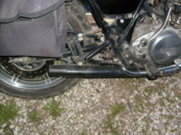
All this is being paired up with an exhaust I partially fabricated this winter. It features a machined spigot that is port matched to the exhaust port (they're flush with one another) and slightly tapers out to the i.d. of the 1 5/8" o.d. primary pipe. The primary carries this diameter until it steps up to 1.75" o.d" after about 15.5" from the manifold face. Then it enters a megaphone/reverse cone before entering the muffler. Total length from the valve seat is ~60". It could be shorter for more peak power, but this set-up clears the kick start and should be faster in the mid-range. Curtis built the megaphone/muffler and the spigot. He also did the tig welding after I tacked it all together. It's ceramic coated inside and out by H.M. Elliott out of Mooresville N.C. (they do a lot of NASCAR stuff).

Before ceramic coating:
photo104_zps486265b1.jpg

photo51_zpsa0278aaa.jpg

primary_zpseb4f496a.jpg


After:
exhaust_zps59a64a26.jpg

This megaphone/reverse cone set-up actually tunes like a true megaphone set-up. The megaphone mufflers don't since there is muffler packing material disrupting the pressure wave.
IMG_1724_zpsd5c7d711.jpg


I'm hoping for some pretty good power out of this. I don't expect anything earth shattering, but I expect it to be more than the typical performance build. We will see...
 
Last edited:
A popular mod on those for racing was a longer rod and cylinder spacer. Wonder if many street motors got that setup?

I haven't seen any on this side of the pond. The SR400, which is still made and sold in Asia is the same exact motor with a shorter stroke crank and longer rod. Some of the European road racers use a REALLY big bore to keep it to 500cc with that set-up. That would probably make for a really good half mile and longer motor as well as it would be a rev'er for sure. Those cranks are really hard to get here, and there might be a few floating around, but I haven't seen them. I made some graphs a while ago plotting the piston speed between the two.


The real problem is the cylinder head on these things. To do them right, you need to add a bunch of material to them. I'm shooting for ~40whp or so with this set-up. I should be close based on others with this cam. If I had about $1000 to give to a cylinder head guy of my choice (that includes valves, beehive springs, etc.), I would expect high 40/low 50s at the rear wheels on pump gas. Considering a bike like mine weighs around 300lbs, that's plenty quick. These engines are really punchy and rip up to about 60mph or so (and still do alright to 100+mph, but they start giving up to the multicylinder stuff up there).
 
Last edited:
I assembled the head tonight after work. Getting everything set up, I'm measuring an installed height of 1.61" for both the intake and exhaust. This works out to be about 130lbs seat pressure, and 290lbs over the nose on the intake (more lift than the exhaust). A quick call to R/D, per past conversations with Harold at Johnson, and a friend of mine who has been building championship winning race engines for 50 years, says I'm on the slight high end for this set-up, but it's nothing out of line, so I'm going with it. I feel I could safely run around 115lbs with this cam. I'm justifying the 130lbs since it is a roller and the ramps are very aggressive looking (need more valve spring). I'm okay on coil bind, now it's just a matter of seeing if the retainer fouls on the stem seal.

I also gapped the piston rings... .016" on the top and .019" on the 2nd. I might get out a fish scale tomorrow and measure oil ring tension. I'm hoping it's somewhere between 15-20lbs.

Here are some photos of the assembled valves:
IMG_1733_zpsb2da849b.jpg

IMG_1732_zps0bed6273.jpg


(I'll move that lock over a hair before finally assembly. It'll probably move on a running engine, but it's annoying me to look at).

And a photo of one of those Raceware nuts and washers. Nothing to ogle at, but a photo might satisfy someone's curiosity.
photo8_zpsae0d4355.jpg


Forgot to add, I'm going to give the modern viton/teflon valve seal a try.
photo58_zps3734f2d1.jpg

Here is one next to a stock one (black).
 
Okay, so I had a bad morning and tried rushing getting the piston together. Double checking the compression ring gap from the other night, I felt it was a hair tight, I ended up opening it up a little too far. :oops: This is what happens when I try to start early before drinking a cup of coffee. My mistake , lesson learned.

So, I've decided to 'upgrade' to a Total Seal ring set. I'll run a gapless top ring and a conventional 2nd. Should be here some time next week.

Some racing engine builders like a gapless top ring and conventional 2nd, some people like a gapless 2nd ring and conventional top, and some don't like them at all. Either way, I don't know of anyone who's tried this set-up in these motors, so I'll give it a shot.

The part number is Total Seal #M3504XC
 
I gapped the rings after work tonight.

Gapped both top rings at .022", the second ring at .019", and the oil control rings are over the minimum .015".

I've already cleaned everything really well once before, but I'll give everything a good cleaning before assembly of piston and inserting it into the bore.

The head is the next and most expensive project on this bike. It is something I'm going to farm out as well. I'm probably pretty far away from doing this though, based on my current work situation. :banghead:

Here is the type of work I would be looking to have done. This is a line of Royal Enfield Bullet heads that were modified by Joe Mondello (rip). Anything I would have done would be in the same 'spirit'. I have a short list of people to contact when I get to that point.

http://www.enfieldmotorcycles.com/forum/index.php?topic=6371.0 (post #6 is a good read).
http://www.enfieldmotorcycles.com/forum/index.php/topic,6763.0.html(photos farther down).

Information on another Bullet head they did for racing (non raised port casting, but did a little welding, with the Harland Sharp roller rocker):

This is a very vintage(1950s) small air-cooled hemi single-cylinder with 535cc displacement and individual runner(of course), with slide-operated carburetor(Mikuni).
Max rpms between 6750-7000 rpm. I'm contemplating flirting with some higher rpms by trying a few mm shorter stroke, but haven't tried that yet.

There are some physical limitations, and the port itself has already been welded to close a break-thru to a head stud hole. Can't go much higher because the frame and tank are directly above.

Stroke is 3.54, and is a 5-piece pressed-up crank.
Bore is 3.425, and the intake valve is 1.84".
80 degree valve included angle.
Port is 4.5" long, including the carb mounting flange which we flow-match to the port entry and pin it in place(shown in photo).
MCSA is 1.5 square inches. (note: this works out to be 35mm round - Bob)
Valve seat I.D. is 1.656"(90%)
Seat angle is 50 degree.
Max lift is .585".
Max flow is 233 cfm at 28".


I know they're making over 50bhp on gasoline with those specs above. To be competitive with the Minnovation G50 Matchless engines, they're going to need about 60bhp or more, which is why they developed this one...

They just completed a factory raised port head. Here are the details:
http://www.enfieldmotorcycles.com/forum/index.php?topic=16411.0(flow results on page 2).

Information on the valves they're using:
http://autos.groups.yahoo.com/group/AcePerformanceBullets/message/3386

And here are the beehives they're using on the low lift set-up:
http://www.racingsprings.com/1200 Series/PAC-1223/item/209

I think they're using a longer stem on the racing stuff, not sure what PAC spring number they're using for it.

I would like to go to a beehive set-up with a tool steel retainer. That would be ideal, imo.

FYI: The source of my retainers also makes a beehive set-up for XS650s:
http://www.ebay.com/itm/23086615536...ries&cmd=ViewItem&hash=item35c0b1f766&vxp=mtr
 
I received a venier sprocket for Gary Hoos and gave it a quick set-up. I also removed the inner valve springs, installed the grub screws to fix the rocker spindle deflection, and tightened the cam chain a bit more to simulate running conditions.

Using hole number "4", position "G" I'm getting:

Intake: 40* BTDC, 65* ADBC ... 285* duration and 102.5* center
Exhaust: 64* BBDC , 35* ATDC.. 280* duration and 104.5* center

Total lobe separation is 103.5* .


Comapred to the published specs:
Intake 40° BTDC 67° ABDC

Exhaust 64 BBDC 35* ATDC

So that's that. I'll check p to v clearances when I get a chance and then bolt everything up for good.
 
Last edited:
Damn dude that roller setup is RAD, this thing is gonna scream

Hopefully! I'm pretty excited to get it together, just my schedule keeps getting in the way.

Here is where the piston clayed with the specs above:
IMG_1811_zpsc2290808.jpg


Exhaust has a huge gap, the intake not so much (~.038")

So I put the pin back in the stock hole and got this:
IMG_1812_zps21cbbd13.jpg


Exhaust gap is still large (~.140"), but the intake has opened up to .055" which is close. I'm torn on retarding it a little more or gritting my teeth and call it a day. It's not going to see over 7500rpm.

photo16_zps3e0ef77d.jpg

I retarded the cam one peg (hole "5" , timing mark "J").

I now have .080" on the intake and still over .1" on the exhaust.

Specs read:
Intake: 36* BTDC, 67* ADBC ... 283* duration and 105.5* center
Exhaust: 59* BBDC , 39* ATDC.. 278* duration and 100* center

103 total.

I'm trying to be as consistent as possible, but there is some deviation as you can tell.

I measured the cam at .050 for shits and giggles.

Intake: 276* duration
Exhaust: 267* duration

Based on the numbers above, I suspect true measurement is 8* less between .040 and .050.
 
Last edited:
I carefully clearanced the intake valve pocket and went back to the original setting (40 open) as seen above.

Assembled the motor for good this morning, and put it in the bike. Had it fired up by about 2pm. It almost went on the 2nd kick, but I had to fiddle with the idle screw and it lit on the 5th. It built oil pressure fast and accidentally had a mini geyser of oil coming from the oil filter bleed, hence the mess under the bike.

I put some heat in the motor and put about ten miles on it riding it up to 60mph or so at 1/4 throttle and then engine braking down to about 20 (without lugging it). I'm letting the motor cool off over night, recheck the valve clearances and chain tension, retorque the head, and then do the same at about half throttle and then full throttle. I'll then change the oil and call it good.

The valves are a little noisy, but that's because the chain tension was still a little loose.

I still have tinker with the pilot circuit a bit. So it's not crisp in the video. The puff of smoke was before I rode it, so it's gone now that it's been ridden a little.

Here's a video of it fired up:

and back together:
photo17_zps6aea5835.jpg
 
Discussing ring gap.

A group of turbo and supercharged Miata builders tried using a standard top ring with Total Seal second rings and it was a disaster. The problem is how a top ring seals. The combustion pressure pushes the ring down in the ring land. This seals the bottom and the ring is forced out to seal the cylinder. With the gapless bottom ring the pressure built up below the top ring and lifted the seal. Combustion blow-by burned out the ring in short order. Since then I have made it a practice to set the second ring gap equal or greater than the top ring.

Tom
 
Thanks TwoMany.. I'd love an old British bike, but I can barely afford this Jap bike. :laugh:

Tom,

Yep. I would never run a gapless 2nd ring. My understanding of things is that materials weren't up to snuff yet to make a gapless top ring work, so they came out with a gapless 2nd. Now that they've gotten them to work on the top, it's what is what professional engine builders use (when they're not using a conventional ring package).

Do I think there is anything to gain over a properly done conventional set-up? I don't. However, I'm not a professional engine builder, so I don't know how tight I can actually make it. So there might be something to gain vs. the 'larger than it could be, to be safe'.

A friend of mine is a championship winning engine builder/tuner (car stuff) going back to the early '60s. He said they always ran at least as large of a 2nd gap as the top... this is when it was common practice to run a tighter 2nd gap. They couldn't explain why at the time (they now know), just that things worked better.

Cheers,
Bob
 
know I made a post previously, but I deleted it and just redoing it.

So this winter, as a college graduation gift to myself, I'm having a cylinder head developed for my bike. I'll also be changing the head pipe when I get the motor back in the frame.

For the cylinder head, I got a hold of a top-notch V8 cylinder head guy who has a lot of experience with Chrysler Hemi's (Nick Smithberg, https://www.facebook.com/pages/Smithberg-Racing/224572780930205 ) and he said he was interested in working on the head as a nice break from his typical stuff.

Things are progressing very nicely with the head. Unfortunately, he had a flowbench issue when he recorded the base line on my cylinder head and forgot to re-base line it before he started making changes. I picked up a junk head for cheap thinking it was stock (had it dropped shipped) to set a new base line and just to use for experimenting purposes. Turns out it had been ported previously, but I didn't realize this until he had it in his hands. Oh well. Here are the flowbench results for the intake on the junk head:
IMG_20140314_141511_447_junk_zps2d481ad7.jpg


We're pretty confident a stock head flows in the 185-190cfm range based on the results of that. That jives up with other flow bench data at 28" depression.

The plan is to make the port as efficient as possible without resorting to making a huge port that is all but unrideable. The port face has been opened up to 38mm (1.50") from the just slightly bigger than stock 36mm (1.42") that my head was previously. Racers tend to open this up to 40-41mm or so. Then most of the work was focused on the short side radius as the port angle enters the head low relative to the valve seat, so it makes for a tight radius and the valve seat / profile. The work isn't done yet, but here are photos of the before and after, as well as the flowbench data for how it is at the moment (the test valve for those numbers was a Harley one he had laying around and picked up some over a reprofiled stock valve. He has the Ferrea profile he wants to use and works on his hemi's coming in and will cut it down and fit it in for testing next).

Before:
IMG_1710_zps47d51d15.jpg

IMG_1709_zps3fce9214.jpg


As it sits now:
IMG_20140307_042846_260_zpsf49f3ca5.jpg

IMG_20140307_043113_127_zps9ad54df9.jpg

IMG_20140307_044412_798_zps2d958ccc.jpg


The port is pretty much developed. He's still playing around with valve tulip profiles and will be going up about 1mm on the intake valve size (47mm to 48mm (1.85 to 1.89")). If you notice, we're killing low lift flow and making a port that comes on STRONG in the mid-high lift ranges. This is an effort to limit overscavenge issues which is an issue for hemi style heads. If you look at VERY high end NHRA hemi heads, they offset the valves slightly to help with this.

While comparing flowbenches is like comparing dyno figures, the port so far is looking really good compared to other flowbench data online for ports that are bigger in dimensions.

On the exhaust side, the exhaust port is monstrously huge with very poor velocity (like in the 220fps-ish range at 28" H20). Nick shrunk and lowered the exhaust valve ( 39mm (1.54") to 37.5mm (1.475")). Again, this helps kill some low lift flow, and the overall velocity profile of the exhaust port should be very better.

Right now we're concentrating on making the carburetor work. I bought a 38mm flatslide to replaced the 36mm roundslide he has been testing with currently. The 36mm roundslide is hurting flow big time. The 38mm flatslide should pick this up some and velocity through it still very good. Velocity stack design testing is the next big thing.

Here is the roundslide on the flowbench yesterday:
IMG_20140315_094949_501_zpsc8cba0e6.jpg


More to come...
 
Last edited:
Back
Top