-
Enjoy XS650.com? Consider making a donation to help support the site.
XS650.com receives a small share of sales from some links on this page, but direct donations have a much greater impact on keeping this site going.
You are using an out of date browser. It may not display this or other websites correctly.
You should upgrade or use an alternative browser.
You should upgrade or use an alternative browser.
Finally got a bike after a few setbacks. What oil, plugs, etc?
- Thread starter wmarsh4
- Start date
The F.
T is for camshaft "timing."
F is for "fire".... you want the plugs to "fire" at that mark.
T is for camshaft "timing."
F is for "fire".... you want the plugs to "fire" at that mark.
wmarsh4
XS650 Enthusiast
Thanks, just watched that 2 times earlier. Probably listen a 3rd time and give it a go. The manual ive downloaded dont mention gaps? Are they the same as mentioned in the video for the 73?
Gap should be the same for all years; .012"-.016"
Rule of thumb: That gap will work for damn near any engine using points... car airplane or motorcycle.
Rule of thumb: That gap will work for damn near any engine using points... car airplane or motorcycle.
I know rookie question do you remove the advance rod to clean and lubeYou really need to service your advance unit too, it's a mess, lol. Also, clean and lube the advance rod so it turns easily and smoothly in the cam.
wmarsh4
XS650 Enthusiast
I don't think im getting any power to the plugs for it to fire. Ohm meter ain't my strong suit. Whats the easiest way to test coils?
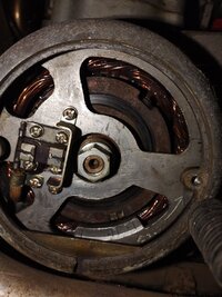
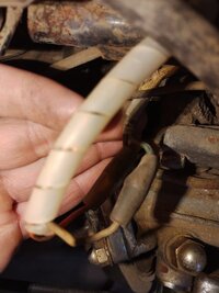
Yes, you remove the advance rod for cleaning it and the bushings inside the ends of the cam that hold the lube (grease) for it. Pull the little round disc off the advance side and withdraw the rod w/ the little points cam still attached out of the points side. You'll see grooves cut into the I.D. of each outside camshaft bushing. If you've never serviced the rod, you probably won't find much, if any grease remaining in the grooves. This is mine after cleaning, greasing, and running it for about 5 years .....

..... and after re-cleaning and packing with fresh grease .....

The shop manual recommends a moly grease of some sort. I use VW CV joint grease as it has a very high moly content.
..... and after re-cleaning and packing with fresh grease .....
The shop manual recommends a moly grease of some sort. I use VW CV joint grease as it has a very high moly content.
wmarsh4
XS650 Enthusiast
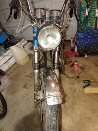
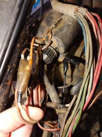
Just a few pics from yesterday morning after i took the tank off. Adjusted the points to what i thought might be correct but still getting no spark. Is there a way to bypass the kill switch so i can rule that out? Headlight control seems finicky so that may be also. Going to try and research how to test coils and other electronics if that aint my issue.
Attachments
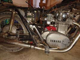
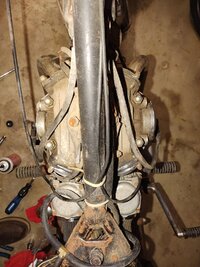

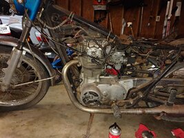

Yes, you could bypass the kill switch. Find the two wires running into it and simply jumper them together. They would be two R/W, two brown, or one of each. But all your wiring looks quite crusty. There could be a bad connection issue anywhere in there, lol. You may need to go through it all. For now at least, you'll need to go through the ignition circuit. Follow the points wires. I see yours are running right on top of the motor. I'd re-route them to up above the top motor mount like so .....

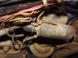
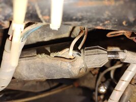
Each points wire connects into a double bullet along with a wire from one of the condensers. I don't see the condenser wires on yours. The wires (gray and orange) with the double bullets run to each coil. The gray should run to the right coil, the orange to the left one.
Each points wire connects into a double bullet along with a wire from one of the condensers. I don't see the condenser wires on yours. The wires (gray and orange) with the double bullets run to each coil. The gray should run to the right coil, the orange to the left one.
wmarsh4
XS650 Enthusiast
Yes, you could bypass the kill switch. Find the two wires running into it and simply jumper them together. They would be two R/W, two brown, or one of each. But all your wiring looks quite crusty. There could be a bad connection issue anywhere in there, lol. You may need to go through it all. For now at least, you'll need to go through the ignition circuit. Follow the points wires. I see yours are running right on top of the motor. I'd re-route them to up above the top motor mount like so .....
View attachment 207320
Each points wire connects into a double bullet along with a wire from one of the condensers. I don't see the condenser wires on yours. The wires (gray and orange) with the double bullets run to each coil. The gray should run to the right coil, the orange to the left one.
Looks like i have orange running to both but i do see the condenser wire you mention attached. They look to be green. Took the crusty grounds off the coil and cleaned that up. Pushed together all plug connectors. Removed black tape and checked under those connections. Everything seems to be touching how it should.
Attachments


wmarsh4
XS650 Enthusiast
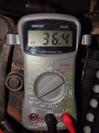
Tried this idk if i tested the primary on the coils on the right setting but i get a zero reading with that. 2 readings here though is what i get when i run a lead into both plug caps unhooked from the plug different meter settings.


Attachments

Last edited:
wmarsh4
XS650 Enthusiast
If i power the key on i get around 13.4 or so reading across coil.Tried this idk if i tested the primary on the coils on the right setting but i get a zero reading with that. 2 readings here though is what i get when i run a lead into both plug caps unhooked from the plug different meter settings.
There are two coil tests you perform, to test the primary and secondary circuits. Note that you don't measure through the plug cap. It's a resistor cap and would add 5K to 8K ohms to your reading .....

Yes, the coils themselves have an orange and a brown wire coming out of them. Follow the orange wires up to their connectors and you should find a gray wire connected to the right one, an orange wire to the left one. The brown wire is power in from the main harness and will be a red or R/W wire. The orange is the firing signal from the points sets.
Yes, the coils themselves have an orange and a brown wire coming out of them. Follow the orange wires up to their connectors and you should find a gray wire connected to the right one, an orange wire to the left one. The brown wire is power in from the main harness and will be a red or R/W wire. The orange is the firing signal from the points sets.
wmarsh4
XS650 Enthusiast
Heres what im looking at. Should the key be on when running this test? Either im doing it wrong and the ohm meter is set wrong or i dont have power there. Either way I've got studying to do. Pretty well froze for the day ain't got above 28°f here. Going to call it quits for the day in the garage and just try and find some info to read on/watch.
Attachments
wmarsh4
XS650 Enthusiast
If i do determine to have bad coils, switching to the single coil dual output would be the better option correct? If i did it correctly this time. It looks like i may be reading 5 ohms on both?I think the coil test you referred to in that gggGary post is for the later single coil with dual outputs. That's a whole different animal compared to your single coils and those tests won't apply.

Similar threads
- Replies
- 1
- Views
- 707