Dead rotor - best options to fix / replace?

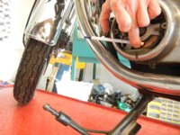
You can check for runout with the rotor installed by removing the brush holder and holding the eraser end of a pencil close to the copper rings with the engine running.

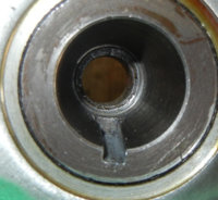
The first video is of a rotor that I bought on line instead of using my better judgement and getting a Custom Rewind. Fortunately, the seller gave me my money back except for shipping costs. The bad rotor also had a defective slot for the Woodruff key.

Kinda a broad hint / clue here...:wtf:...did anybody with the defective Woodruff key slot also check their runout? Huh? :doh:
 
Yeah I hear you Pete. I'm going to look at the runout. But..... Like you show above without comparing the runout of the original rotor in the same crank it doesn't mean much. These cranks (like all pressed cranks) are prone to movement at the joints. I watched both videos and to be honest I am not 100% sure what you are showing. Showing rotational movement with the low frame rate of typical video that is filtered through several sets of transfer with possible frame dropping is frustrating at best.
I think I can grab the original rotor and do back to backs with a dial indicator. see what that shows.
The racetech rotors are/were being offered at a deep discount and that IS a red flag.....
I have a second untouched racetech in the box and a (ancient) lathe, but don't have a live center for the tailstock. guess I can set it up, use oil and a lot of caution. Can't tell how you are holding, what you are using for center on the back side of the rotor.
PS I got 5.6 ohms on that second rotor also.
 
gggGary,

Look where I have the cutting tool positioned. You will see the surface of the slip rings distance to the cutting tool vary quite a bit as compared to the other video of the Custom Rebuild rotor. Remember that the custom rebuild rotor was OEM.
 
Handheld dial indicator, on an 82 e-starter, plugs out, first run, will try to check a few others.


I thought I was able the get the dial indicator quite stable on the stator and in the middle of it's travel. I'm coming up with .006" ish.
So is that acceptable? Is it rotor or crank that is causing the runout?? I will try to get a feel if that's "normal" or excessive????
This is nothing like the "wobble" I think your lathe video is showing....

Note; I used "two plugs connected with grounded bare copper wire" to keep "sparky" happy!

A video I did last fall after I roached the 79 crank.


It wobbles :yikes: but it ain't the rotors fault!
 
gggGary,

If the subject is rotor runout, then whatever crank irregularities there may be is not relevant to the rotor. However, checking for overall runout with the rotor mounted on the crank is useful in determining the problems associated with the irregular contact of the brushes to the slip rings.

I don't know if .006" is excessive. Is there any evidence of carbon buildup (valleys) with some patches of copper showing (peaks) on the slip rings?
 
Don't see any hill/valley evidence, the outer ring is uniform in appearance. I suppose a guy should take a look in a dark room when running/charging.

Not many guys have a lathe set up to check runout. How much of the runout is crank vs rotor seems relevant to me. No matter how perfect the rotor if the crank wobbles it all wobbles. That's why I'll try to get a few different bikes measured, try to establish a "normal" baseline?????
 
gggRary,

Well, the relevance is that excessive rotor runout is easily cured so it is useful to know what the rotor runout is and that can only be determined with the rotor off of the crank.
 
I might suggest checking the old rotor before removing then checking again when the new is installed. If it's no worse, you are as good as it's going to get.
I should really pull that rotor and deepen the keyway a smidge.
Your warning on the quality of "new" rotors (likely from Hu Flung Dung mfg.) is well headed.
 
So, how much runout is tolerable? Suppose we calculate the max 'G' loading on the brushes, for a given runout value and engine revolutions. (The max 'G' loading occurs at the valley and inversely at the peak of the runout)

What I come up with is roughly:

G = Rm x Krpm^2 / 70

Where:
G is G-load, 1G= earth gravity
Rm is runout in mills (0.001")
Krpm^2 is Krpm squared
Krpm is thousands of rpms, 6000 rpm would be 6 Krpm

So, in gggGary's case, where he observed a runout of 0.006", the Rm value would be 6
If idle is 1200 rpm, the Krpm value would be 1.2
At the high end, let's use 8,000 rpm, of which Krpm would be 8
So, the G-loads for idle and hi-rpm would be:

G = 6 x 1.2 x 1.2 / 70
G = 0.1234 (at idle)

G = 6 x 8 x 8 / 70
G = 5.5 (approx, at high rpm)

The brush spring would need to counteract this 'G' force to keep the brush from floating off the slipring at the high point of the runout. If the brush weighs 1 ounce, then for this example, the spring should be pushing at least 6 ounces to prevent brush float.

I don't know the weight of the brushes, or the spring rate. Have some new ones out in the barn, I suppose I could go out there and figure this out. But, knowing those, might be able to come up with a viable limit to rotor slipring runout.

Anybody want to check my math?:shrug:
 
TwoManyXS1bs,

Excellent workup! It also points out the other problem with too much rotor runout and that is the output of the alternator will decrease as the RPM's increase due to brush float. :wtf: If you could come up with a tolerance for runout that would be useful for checking the quality of a rotor. :thumbsup:

PS: I don't think anyone is going to challenge your numbers! :laugh:
 
TwoMany......................I think you're on to something, but my head hurts from trying to follow the math. I wonder if the co-efficient of friction for carbon and copper should also be considered if we are to really solve this:)
 
RG,

The material for the slip rings is supposed to be an exotic alloy of copper and some other metal to provide less friction for longer brush life, but as I said, supposed to be. In some of the lower cost rotors I would imagine that would be an area for cost saving...:D

Some years ago when I was younger and my brain worked better, I did a little research on the subject and was astounded at the complexity of brush to slip ring science primarily for large power plant generators where the brushes are carrying hundreds of amps and running 24 hours a day. There are some graduate students doing their thesis on the subject it is so arcane, so our little application is not as rigorous, but some of the principles apply, except now I can't remember what those principles were. Oh well..:shrug:
 
Been testing, had about 4 rotors off and on a couple of times each.

A dial gauge on the outer edge of this 82 crankshaft taper; about .001" of runout,
A stock used rotor on the outer slipring about .002"-3 I'll call this about a baseline, .001" on the crank probably translates to about 2 or .003" measured further away from center. The racetech; with the taper bore cleaned up with fine paper, edges of keyway filed down, slip rings sanded with fine paper evenly all around now also showing about .002-3" of run out. A second racetech tested "fresh out of the box" came in at about .008-10" of runout. So if you use a racetech... Expect to remove the shellac from all surfaces, file out the raceway, sand the slip rings and taper bore. And it still might be a crap shoot to get "acceptable" runout. The machining in the taper bore is a touch crude, same on the slip rings. I'll guess typical sloppy work, dull tools results.

For the DIY I have a method using only an ordinary stick pen to check run out. I'll post video of that and other tests later.
I counted and have about 15 used rotors on the shelf, about 1/3 still test "in range" for ohms ie between 5.1 and 5.8 ohms, it's a biased sample, swapped out "bad" rotors go back on the shelf for use as rebuild cores?

2many; that deep math stuff is all yours!

Now I gotta go put that poor 82 test mule back together!
It has a very good battery (farm & fleet lead acid) it cranked the engine a bunch with no running.
 
I was hoping mrriggs would jump in on this. Gets lonely out here in mathland. I'll be out in the barn today, goofin' with brushes and springs, will post findings later...
 
videos and pics of runout testing etc.

Pen test set up like pete's pencil test I'll guess
rotors 002.jpg


taper bore racetech
rotors 011.JPG

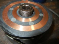
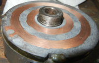
racetech slip rings as delivered
rotors 013.jpg

racetech sliprings after cleanup

rotors 012.JPG

gauge setup


Running with the heavily discharged battery and racetech.


Now with a fully charged battery.


All taken with a nikon coolpix s8100, grabbed off craigslist last night, very nice camera, they sold new for about $300, now used for $50 to $100 :thumbsup::thumbsup: No one wants digital cameras anymore I guess. it's all phones.
 
The effects of rotor slipring runout. Potential for brush float and bounce?

Please excuse the following garble, and some liberties with approximations. It's just how my head works. This is when a chalkboard, and room for arm flailing, is very handy.

You can skip thru all this and just see the important thing is at the bottom of the post.


Here, I used a screw and threaded sleeve as a depth gauge to measure the working zone of the XS brush and spring, from the slipring surface to the spring basepoint of the outer brush mount. This measured as 0.895" (almost 23mm).
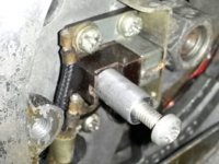
XS-Brush-Depth.jpg


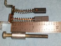
Half worn factory brush is on top, new MikesXS brush is atop the ruler.
At the bottom is the depth gauge for comparison.

The spring is just barely compressed, almost 1 inch long, so we'll just say that it has a free length of 1.000" (25mm).
The spring's OD is 0.174", with a wire size of 0.014", and has 13 coils, of which 11 are active coils.
Reverse engineering the spring with the online spring calculators (to get the average spring rate) yields 1.20 LbF (pounds) per inch.
This equals a spring rate of 544 grams per inch.
XS-Brush-Length.jpg


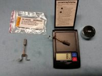
Weighing the XS650 brush. Didn't want to unsolder the thing, so I set the brush on the scale's weighing pad, with the mount bracket on the edge. That should eliminate the bracket and about half of the spring from the measured weight. The scale shows 8 grains, we'll just say it's about 0.50 Grams (0.0183 ounces).
XS-Brush-Weight.jpg


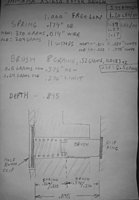
A pic of my notes (subject to subtle revisions):
XS-BrushNotes.jpg


When new, the brush's rectangular body length is 0.575" (14.6mm). The wear limit line leaves a brush length of 0.275" (7mm). So, we'll just say that the weight of a worn brush is about 0.24 grams.

When the brush is NEW, the spring is compressed down to 0.320" (0.895" working depth - 0.575 brush length).
This produces a compression of 0.680" (1.000" freelength - 0.320").
This 0.680" compression yields a spring force of 370 grams (0.680 x 544 grams per inch).

When the brush is WORN DOWN to limit, the spring is only compressed down to 0.620" (0.895" working depth - 0.275 brush length).
This produces a compression of 0.380" (1.000" freelength - 0.620").
This 0.380" compression yields a spring force of 207 grams (0.380 x 544 grams per inch).

So,
When NEW, the 0.50 gram brush is held by 370 grams of spring force. It can get 740 G's of acceleration (370 / 0.50).
When OLD, the 0.24 gram brush is held by 207 grams of spring force. It can get 863 G's of acceleration (207 / 0.24).

Kinda interesting, huh? A worn brush is more likely to follow a wobbling/runout slipring.

Now, using the above formula:

G = Rm x Krpm^2 / 70

Where:
G is G-load, 1G= earth gravity
Rm is runout in mills (0.001")
Krpm^2 is Krpm squared
Krpm is thousands of rpms, 6000 rpm would be 6 Krpm

Let's use 8,400 rpm as the extreme limit for determining 'G' acceleration force on the brush.
This simplifies the formula, since 8.4^2 / 70 = 1, so we're left with:

G = Rm

What this means is that for every 0.001" of runout, you will need 1 G of accelerative force on the brush to keep it on the slipring.

If the stock spring can provide anywhere from 740 to 863 G's of acceleration, then the tolerable runout can be as much as 0.740" to 0.863". (!!!)

Of course, this is WAY beyond the clearances in the alternator shell, and clearance to the brush holder.
So, unless someone can offer a less ludicrous analysis, I'd have to say that rotor runout will never induce brush float.

I suppose the next question should be: How much pressure (force per unit area) is required to maintain good current flow in a carbon/copper slipring application? Is there a relationship between pressure and ampacity?

(*whew*)
 
:bow2: You are the math king of XS650 2many :bow2:


Same set up as above with a fully charged "known good" battery.


In the earlier run the battery had enough juice to e-start the bike easily. Interesting how far an undercharged battery pulls down the system.
 
Had to shutdown again and switch over to other machine to see your videos. I like the 'sensitive' plastic pen runout indicator.

Several years ago I pulled the side cover and alternator housing on the stocker, and 600 grit sanded the rotor while the engine was idling. Just cleaning it up. Had no discernable runout during this, never considered that this would occur and/or be an issue.

I understand the uneasiness over rotor runout, makes my skin crawl just looking at ya'lls videos.

I'd like to check mine while the engine is idling, but 1200 rpm is a bit too fast for my indicators, so will cogitate on this for awhile...
 
TwoManyXS1bs,

Can I guess that being as you are in Texas, that you worked for NASA at some point? The next thing to investigate is whether the change in pressure on the brush causes a buildup of carbon in the valleys and a cleaner slip ring segment in the peaks. This would result in a higher resistance in the valleys which would in turn reduce the average attainable current in the rotor windings and a subsequent lowering of output voltage.
 
Back
Top