Engine heating up and shutting down

Without me reading back through....
What happened when you grounded the green wire?
 
1696111554670.png
 
This means I will have to remove the entire housing , I removed the outer plate and I could not get those tweezers in. Is there a simpler way to get two of those bolts without removing the entire housing. I will have to also remove the gear shift lever

*Can I not use the screw on the top part of the stator instead of the side one ?

1696120596835.png
 
Last edited:
This means I will have to remove the entire housing , I removed the outer plate and I could not get those tweezers in. Is there a simpler way to get two of those bolts without removing the entire housing. I will have to also remove the gear shift lever

*Can I not use the screw on the top part of the stator instead of the side one ?

View attachment 252359
You can ground it anywhere there's metal... doesn't have to be the screw holding the stator.... anywhere on the stator's fine.
 
Some thoughts

Stator dont break down so often it happens but is more rare than rotor
You have replaced it ( where is the old one for measurements or money back refund .)
If the suggested measurements above dont make sense

I would connect everything and measure charging Voltage to get a baseline
across battery everything off
across battery ignition on
across battery started .at 3 - 4000 rpm

Is it still 13.5 ish and the same as battery has everything off then we have a no charging situation.
Possibly rotor or Reg /Rectifier if the stator is replaced.

About The regulator rectifier combo on the table off the bike -- is anything more known about that
Documents .... perhaps possible to connect further on ?
 
Well the moment you turn the ignition on ( don't have to start the bike), the battery drain starts pretty rapidly. So if you start bike , rev the RPM and I have done all that the results are going to be any different. My results are documented.

What's frustrating, even in the tests where we disconnected the reg/rec, we don't seem to be getting the required voltage on the wires from the Stator. If the stator wires don't receive the voltage while the bike runs/revs , it will pass nothing to the reg/rec.

The ref/rec and relay combo that was removed were original. I mean its only 6 months since I have owned the bike. But again - I wonder why I should not get readings from the stator while the bike runs. The Slap Test works so the rotor is good.

I do want to remove the fuse from the fuse box that connects all the lights . Does anyone know which are pertaining to them ?
 

Attachments

  • fuse.jpg
    fuse.jpg
    161.7 KB · Views: 26
Last edited:
Did you already check the resistance between the 2 copper slip rings on your stator? I know you did the slap test, but it's worth getting an actual number, just to be sure.
 
Did you already check the resistance between the 2 copper slip rings on your stator? I know you did the slap test, but it's worth getting an actual number, just to be sure.
Will get it done in the next hour. I am one man so I have to figure a way to tape the multimeter probes, hang my multimeter and then I'll be able to hold the pliers and the rev bike with the other.
 
The slip ring test is done with the engine & ignition off. It's super simple.
Literally just touch the probes to the slip rings & gets an ohm value.
If you haven't removed the entire timing cover & you just have the center, circular cover off, you'll need to remove the left hand side brush to access the outer ring.
Doesn't matter which way round the probes are.
First test is to touch the probes gently to the rings.
Second test, use the probed to lightly scratch through the outer surface & test the clean spots.

If there's enough crud built up on the ring faces, the brushes won't make a good contact. Also, check your brush length to make sure they're within spec. There's a 'wear limit' line on them. If you can still see it, you should be good.

Again, I'm no electrics whizz, but it seems to me that if the rotor is energizing & the stator is good, it simply might not be getting power from one to t'other.
 
Can I do these tests removing the fuse for the head and turn signals. Appears the middle two are the ones pertaining to them ?

1696166348535.jpeg
 
Can I do these tests removing the fuse for the head and turn signals. Appears the middle two are the ones pertaining to them ?

View attachment 252378
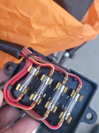
I find the fuse removal optional, but the book does say that, so you can remove the headlight fuse, but leave the turn signal fuse in-place: (depending on how the harness is wired that fuse is needed to power the brushes)
 
All, I've got some big positive news. I removed those two fuses in the middle and it has made a sea of difference. Because I had a feel the work around the turn signal wiring is a little douchy.

1. Turn the ignition on , the battery does not suck as bad.
2. Rev'd the engine and it now goes upto 13.6 and 13.7 still not 14 but the battery at idle stays at 13.00 and even climbs slowly.
3.Did the green button test with pliers and yes Voltage goes up to 15 and 16. - Note with the light Fuses on , it would not go beyond 13.

Maybe the regulator is a problem so is the wiring of those turn signals. Thoughts....

I am not sure if I will get a 14 .5 on revving if I pop back at least one of the fuses.
 
Last edited:
All, I've got some big positive news. I removed those two fuses in the middle and it has made a sea of difference. Because I had a feel the work around the turn signal wiring is a little douchy.

1. Turn the ignition on , the battery does not suck as bad.
2. Rev'd the engine and it now goes upto 13.6 and 13.7 still not 14 but the battery at idle stays at 13.00 and even climbs slowly.
3.Did the green button test with pliers and yes Voltage goes up to 15 and 16. - Note with the light Fuses on , it would not go beyond 13.

Maybe the regulator is a problem so is the wiring of those turn signals. Thoughts....

I am not sure if I will get a 14 .5 on revving if I pop back at least one of the fuses.
Sounds reasonable to me. Continue the testing to identify possible excess draw on the signal circuit
 
So I guess when I asked my mechanic to hookup the turn signals for the retro looks , he took up some short cuts and inter-twined the headlight and turnsignal circuit. With one fuse back on, the results are not substantialy better but I atleast get my neutral light.

I have two questions :
1. I get 13.5 max on revving maybe 13.7 , should I mount back the old regulator and relay
2. Should I ask the mechanic to do the wiring and fix the problem and verify it Or how big of a daunting task is it to do it yourself.

What's the undertaking here. I am extremely grateful for all the support so far. Thank you.
 
Are the turn signals powered through the headlight fuse (red/yellow wire), rather than signal fuse(brown wire)?

What are charge readings @ battery with headlight fuse removed and signal fuse in-place?

What is charge reading with headlight fuse in-place and signal fuse removed?
 
Are the turn signals powered through the headlight fuse (red/yellow wire), rather than signal fuse(brown wire)?
YES !!! . Thats what he's done. . The brown powers the NEUTRAL led.
What are charge readings @ battery with headlight fuse removed and signal fuse in-place?
So If I remove this troubled fuse. I don't get Head Light and Turn signals. Having them on the battery loses power continuously on idle and ignition on. Having this fuse revving I can get max to 13 . Without them it goes upto 13.6

1696173759567.png
 
Last edited:
Hmmm........it'll take some doing -and perhaps some replacement connectors - but the signal circuit (flasher, etc) and neutral circuit should be powered off the brown wire. IDK what effect the current re-wiring is having on the overall output, but perhaps including the signal circuit in the headlight circuit creates too much constant draw. You need to do some poking around to verify, but I imagine that the place to start is at the flasher (under the tank) to see what is supplying power there. :umm: There is a good diagram for the proper wiring on an xs650SH here in tech section - it'll be maybe a weekend project to re-wire.
https://www.xs650.com/threads/some-wiring-diagrams.61/ (post #7)
 
Last edited:
Back
Top