Expanded charging system guide (In progress)

I've been looking into solid state regulator/rectifier use on my kickstart only '73 TX650 with the standard alternator. It occurs to me that part of the reason for a poor spark at startup is the voltage drop introduced when the load of the rotor (typically 2.2 amps) is applied when the ignition is switched on. A decent battery should be able to better power the ignition alone (points or electronic), without the alternator rotor load. Therefore, why not use the yellow wire from the alternator to trip a relay that switches on the alternator rotor power after the engine is running? The yellow wire is normally used for the safety cutout relay of the electric starter. Anybody tried this?
 
Welcome to the forum Johnwaters. Yes, that's an excellent question and project, how to delay the rotor current demand until after engine start. Some backround info on power demands:

http://www.xs650.com/forum/showpost.php?p=363526&postcount=116

With the yellow wire, the problem is that it won't produce any voltage until the rotor is energized.
 
Last edited:
I just read this whole thread. In the first few posts it talks about how to test the 80 systems, nothing about the 70-79 systems.
Hmmm, Maybe a rewrite is needed.
Leo
 
I just read this whole thread. In the first few posts it talks about how to test the 80 systems, nothing about the 70-79 systems.
Hmmm, Maybe a rewrite is needed.
Leo

Yes Leo, the thread focuses on the 1980 to 83 years. I find a lot of guys just can't wrap their heads around the differences, between the early and late alternators.

I think it was Pamcopete that suggested the idea of using nylon screws for the brushes, which was a clever mod, but has caused a lot of confusion. Not Pete's fault, its just that some folks are easily confused when it comes to electrical things.

In posts #77, #80 and #113 I have tried to explain when the brushes need a ground and when they are insulated. It seems simple enough to me. I suspect that most lads are looking for a quick answer, and don't spend the time to read any threads that are longer than a few pages. The answers are all here in the threads, but it does take some reading comprehension.
 
I've been talking with a fellow by PM's, He was trying to test his 78 or 79 alternator using the Guide and was confused by the way the guide does the bypass test and the way I described the bypass test.
I work with him a bit more.
Leo
 
I've been pondering on exactly the same thing for quite some time now, how to delay the rotor current demand until after engine start. Some backround info on power demands:

Route the rotor voltage control through the normally closed contacts on a 30A automotive relay. Wire the relay coil input to the 12V output of the starter solenoid and run the output to ground. When the starter button is pressed, the 12V activates the relay coil, opening up the electrical path to the rotor so that it is not magnetizing. Once the motor is started, and the starter button is released, the 12V to the relay is removed, and the normally closed contacts re-establish the electrical circuit to the rotor allowing it to charge. The auto style relays are less than $10 in some places. If the relay ever fails, it won't leave you stranded, since the rotor will be charging normally due to the normally closed contacts completing the circuit. Simple.

relay-5C_large.jpeg


Contact 87a is the normally closed contact, 87 is the normally open contact, and contacts 85 and 86 control the relay coil to switch states. Contact 30 would be the rotor magnetizing current. Wire contact 87a to wherever this wire would normally go without the relay in line.


You could use a 12V true-off timed relay, but that's getting unnecessarily expensive.
 
Yes, you can wire up circuits such as MacMcMacmac suggests, but the reality of the matter is that there simply is no need to do so. To do so, means you are trying to mask an electrical weak area on your bike.

If your engine has trouble starting due to the rotor current pulling down the voltage, then your battery or your wiring/ connectors etc are defective in some way. My engine always starts using the starter motor and with the rotor current flowing.

I suspect that most "failures to start" are due to weak/worn out batteries, and worn out ignitions/wiring.
 
After sitting for 3 months my 79 with factory charging components, and a pamco started on the third kick at 22 degrees F, I hadn't even trickle charged the battery since I parked it. I put on 20 miles with heated vest and chaps plugged in the whole time. Ran perfectly. My changing color LED showed a positve charging rate starting at about 2K with the big load on the system.

Youse guys are right about the guide, a quick how to tell if you have an early or late sytem then a separate section for how to test each? It will still leave the guys with a PO's mish mash of parts confused, but there is only so much we can splain to em.

Anyone want to do or modify a early how to trouble shoot guide? I would be happy to change some early posts in this thread to steer them to it.
 
I have also just waded through this entire thread and to be perfectly frank its just too wordy and full of extraneous stuff thats not needed.

I'm a persistant sob so I read all of it but most owners looking for a simple clear troubleshooting guide are not going to have either the time or inclination to wade through 7+ pages and be able to retain it all. All the questions and discussions about modified wiring systems and non standard components should be kept seperate in order not to confuse the issue

What is needed in my humble opinion is a simple troubleshoot flowchart and a seperate simple pictorial troubleshooting guide with a completely seperate thorough tutorial with a clear explanation of how the charging system works , the components , modifications, upgrades and model year differences as a locked sticky

Its too unwieldy to try incorporate the lot together in a single guide.

People need to see clearly how to test their charging system without necessarily having to wade through complicated explanations of how it all works.

Personally I like flowcharts but most folk will find it easiest to follow a video troubleshooting guide .Carbon Airwolfie Anlaf and others have done some excellent video tutorials and they have clearly been extremely helpful if the number of positive feedbacks and thanks are anything to go by.

I'd be happy to contribute to producing something but I only the components for have a 1979 model
I did do a quicky video a year ago but it was crude and contained some inaccuracies and needs a complete makeover showing testing done on the bike as well as when the rotor and stator are removed
 
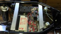
I've built a minimal, kick only, charging system now for my 1973 TX650 using the tiny Yuasa NP0.8-12 battery (see picture below). This system runs my Boyer ignition box fine, even though the standard alternator rotor windings are powered when the ignition is first switched on. The complete assembly fits onto a small alloy plate under my seat and is mounted on the standard battery box mounts to minimise vibration problems.

See my complete build here: http://yamneggs.tumblr.com
 

Attachments

  • 2014-11-28_15-28-03_198.jpg
    2014-11-28_15-28-03_198.jpg
    154.9 KB · Views: 300
lovely job John fits very well under the seat , thanks for posting :thumbsup:
 
Very nice work Johnwaters! please report back when you get some miles on it. No reason to worry about vibration on an XS650.........
 
I have a 07 johnny pag frame with a 82-83 xs650 in it. as I go through the test I come to the green wire test. my green wire has power so when I ground it I pop the fuse. do I need to unplug the wire and ground it in the regulator rectifier side???? thanks
 
Since you have an "unknown" charging system it will be a bit harder to trouble shoot.

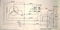
Here is the "as the factory wired it" late model diagram

View attachment 34827

hat may or may not be what you have installed on your bike.
The way factory did it 80-84, the brown brings + 12 to one brush, the green grounds the other brush through the regulator as needed to complete the field circuit and provide the correct level of charging/voltage output by the stator.

Would be good to see pic inside of your LH cover and maybe the voltage regulator part # and a pic.

Once someone starts rewiring all bets are off for color, routing etc. I seen some pretty bizarre wiring on these.

Genaric Alternator circuit with a field coil, grounded through the regulator.

suzuki-gsxr1100-generator-electrical-circuit.png
 
yamapag, Some pics of what you have will help us help you. With the round cover on the left side of a good pic showing what's inside, as well as a pic of your reg/rec.
This will help us id what you have.
Being acustom built machine it could have anything. You might contact the builders and ask what they used.
Leo
 
me and a friend built it. I have power out of the green wire and the brown wire. I tried to post a pic of the diagram that I used but this page wants a url. grrrrrrr lol
 
Upload your pic to a hosting site and use the url from that. One I use a lot is imgur, but the quick and dirty upload for forums is this one...
http://www.freeimagehosting.net/account.php
Ignore 'account' it's free. Just upload, get the url and trim it to suit - get rid of the bits before and after teh core of the image address, leaving something like this in...
http://i.imgur.com/pKJgZ8h.jpg

pKJgZ8h.jpg
 
Back
Top