-
Enjoy XS650.com? Consider making a donation to help support the site.
XS650.com receives a small share of sales from some links on this page, but direct donations have a much greater impact on keeping this site going.
You are using an out of date browser. It may not display this or other websites correctly.
You should upgrade or use an alternative browser.
You should upgrade or use an alternative browser.
First time rehab of a 1976ish basket case
- Thread starter LiveSlowDieWhenever
- Start date
The more tools you have, the more stuff you can fix! (my wife doesn't buy it...) 
You might find this thread in wiring handy... http://www.xs650.com/threads/wiring-harness-musings.18925/ ....Personally i prefer to crimp the wire and then a drop of solder if wanted........Connector will actually grab and hold the wire, if soldered first then the connector only wraps against the solder
http://www.ktm950.info/how/Electrical Shop/Wiring/Basics/Basic_wiring.html
http://www.ktm950.info/how/Electrical Shop/Wiring/Basics/Basic_wiring.html
Exactly right. Crimp first then just a tiny drop of solder. As soon as it starts to flow.... stop.Personally i prefer to crimp the wire and then a drop of solder if wanted........Connector will actually grab and hold the wire, if soldered first then the connector only wraps against the solder
LiveSlowDieWhenever
probably broke down. Just call me greasy.
Thanks 650, I actually read a bunch of that thread before I joined the forum, but I'll go through more thoroughly as I close in on wiring day. I assumed that if you heated to the right temp, the tinned wire's solder would fuse to the fresh bead on top. Everything's getting heatshrinked.. shrunk... shrunken.. anyway I'm just being anal. I'll do some experiments and post results with rudimentary pull tests when I startYou might find this thread in wiring handy... http://www.xs650.com/threads/wiring-harness-musings.18925/ ....Personally i prefer to crimp the wire and then a drop of solder if wanted........Connector will actually grab and hold the wire, if soldered first then the connector only wraps against the solder
http://www.ktm950.info/how/Electrical Shop/Wiring/Basics/Basic_wiring.html
LiveSlowDieWhenever
probably broke down. Just call me greasy.
Never mind, that's two more experienced minds (yours and jims) both saying to solder post-crimp, so instructions i shall followThanks 650, I actually read a bunch of that thread before I joined the forum, but I'll go through more thoroughly as I close in on wiring day. I assumed that if you heated to the right temp, the tinned wire's solder would fuse to the fresh bead on top. Everything's getting heatshrinked.. shrunk... shrunken.. anyway I'm just being anal. I'll do some experiments and post results with rudimentary pull tests when I start
Thousands(?) of years ago, one of my electronics instructors told us something I already knew: "...the key to a good electrical solder connection is a good mechanical connection..." 

LiveSlowDieWhenever
probably broke down. Just call me greasy.
So that's 3 in favor of crimp first ask questions later?Thousands(?) of years ago, one of my electronics instructors told us something I already knew: "...the key to a good electrical solder connection is a good mechanical connection..."

LiveSlowDieWhenever
probably broke down. Just call me greasy.
Just about all diagrams have the red wire from the regulator splitting off to the ignition and then a fuse before the battery. Should be red wire from regulator through a fuse to the battery and run to the ignition as a split off there.......
Not sure if the starter button blue/white wire should run to the safety relay.........
Blue/white from the solenoid to the starter button. When the button is pushed it contacts a ground and starts.....
Not sure if the starter button blue/white wire should run to the safety relay.........
Blue/white from the solenoid to the starter button. When the button is pushed it contacts a ground and starts.....
Last edited:
LiveSlowDieWhenever
probably broke down. Just call me greasy.
For that red wire, did you mean coming from rectifier? In that case, do you mean ign hot should come from the battery side of the fuse?Just about all diagrams have the red wire from the regulator splitting off to the ignition and then a fuse before the battery. Should be red wire from regulator through a fuse to the battery and run to the ignition as a split off there.......
Not sure if the starter button blue/white wire should he connected to the safety relay.........think it should be to an earth.........???
As for the safety relay, I'm gonna keep reading and researching until I can either concur or disagree, but for now we'll say you're right, since you probably are
 also that is a wayyy tidier and official looking diagram, definitely seen it before! 10/10 does not look like a 6 year old drew it
Last edited:
LiveSlowDieWhenever
probably broke down. Just call me greasy.
Dang, I was excited to finally contribute something after all the questions too..No, those no-hole pilots you found are not compatible with your carbs. They are actually a no-hole version of a BS30/96 type pilot and you need VM22/210 pilots.
LiveSlowDieWhenever
probably broke down. Just call me greasy.
That's gotta make more sense than blue/white going into the old smoke and mirror box and coming right back out magically transformed into a black ground wire!Blue/white from the solenoid to the starter button. When the button is pushed it contacts a ground and starts.....
Revised and finished the Diagram with the second stop switch and power, (red), to safety relay and renamed solenoid and start switch
LiveSlowDieWhenever
probably broke down. Just call me greasy.
It's starting to make sense. Gonna take me some time, virtually no electrical experience. Methodically reading thru every wiring write up I can find until things start to look less like a foreign language. Thanks 650Revised and finished the Diagram with the second stop switch and power, (red), to safety relay and renamed solenoid and start switch

LiveSlowDieWhenever
probably broke down. Just call me greasy.
I'm down and out for the night, stay tuned for more mediocrity and watered down explanations! 

been working on this XS2 wiring diagram...........
Any faults found please advise to revise...
You found the missing front stoplamp switch. Good.
The fusing for the battery is correct in the original diagram.
The battery is capable of dumping hundreds of amps to shorts in the wiring, so must be fused. The rectifier can only put out a dozen or so amps, not enuff to fry wiring or blow a fuse.
Like this:

Wiring diagrams for these early models have a problem depicting the blue taillight wiring. A bit confusing, but only the taillight is powered in the "park" position, yet it and the instrument bulbs are all powered when headlights are on. The factory diagram shows only the blue taillight wire coming from the ignition switch's "park" position, yet no provision to power the taillight with the instrument lights. I have yet to see a wiring diagram that explains this. I had this figured out long ago, but it's gone.
I see you've also modified the starter button.
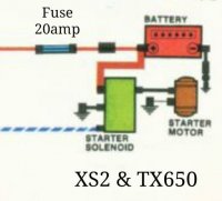
Here's another excerpt of the XS2-TX650 starting circuit, with the safety relay.

Last edited:
I removed the diagrams to save confusion. I started a thread asking about this as well. I will work through there...........
Are you saying the Yellow from the alternater doesn't continuously power through the Safety relay to the brown wire onto the Red/white wire.......??
Would the blue wire from the bar switch on/of switch, connect up to the taillight off the Blue meter light circuit ??
Are you saying the Yellow from the alternater doesn't continuously power through the Safety relay to the brown wire onto the Red/white wire.......??
Would the blue wire from the bar switch on/of switch, connect up to the taillight off the Blue meter light circuit ??
